Hardware Reference
In-Depth Information
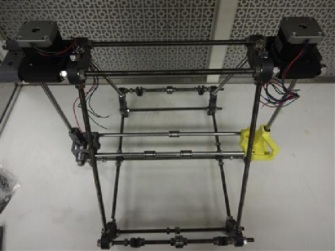
FIGURE 5.19
A completed frame with
x
,
y
and
z
.
The last step to complete the main portion of the mechanical assembly is to atach the
x
-stage
to
z
-stage. Take the couplings that couple the shaft to the motor and clean them out. These
couplings take a pair of M3 × 20 screws and M3 nut and M3 washers and they it into the nut
traps on the coupler. Mount the coupler and the
z
-axis threaded rod (210 mm M8 threaded
rod) as seen in
Figure 5.20
.
Please note that the couplers are printed in ABS for flexibility. The
coupling ends may need to be reamed out with a drill bit, however, ensure that there is a snug
arily tie it to the top frame and put two M8 nuts on the
z
-axis threaded rod on both sides.
Search WWH ::

Custom Search