Graphics Programs Reference
In-Depth Information
1.
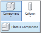
Open the Level 1 plan view. Go to the Architecture tab's Component
flyout, and click Place a Component.
2.
From the Modify | Place Component contextual tab, click the Load
Family button; under the
Furniture
folder,
Seating
subfolder,
choose the
Chair-Executive.rfa
(
M_Chair-Executive.rfa
) family.
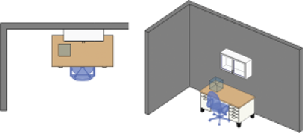
Place it as shown in the left image in Figure 6.14, making sure the
chair is centered under the desk's opening.
Figure 6.14
Loading and placing the chair in the project
3.
Select the desk. In the Type Selector, choose the 72
″
× 36
″
(1830 ×
915 mm) type.
The changes in the desk dimensions are applied from the upper-
right corner; therefore, the chair is no longer centered and will have
to be moved. If there were many chairs and desks in this situation
(such as in an office layout), this task would be very tedious! Let's
change the insertion point of the desk to avoid this situation in
future design iterations.
You may need to press
the Tab key several
times while the cursor
is over the horizontal
reference plane
because of its close
proximity to other
geometry.
4.
Select the desk, and click Edit Family in the ribbon to open the desk
in the Family Editor. Open the Ground floor, floor plan view.
The insertion point of a family is determined by any two reference
planes that have the Defines Origin property. In the next step, you
will change the reference planes with this parameter.
▶
5.
For each of the two reference planes (highlighted in Figure 6.15)
select the plane and select the check box for the Defines Origin
parameter in the Properties palette.


Search WWH ::

Custom Search