Environmental Engineering Reference
In-Depth Information
3.2.2.6 Operation at Given Stator Current
Consider the case when the machine is fed by impressed currents or from a current-
source inverter, terminal voltage and torque are calculated, using the same equiva-
lent circuit model, as follows:
1 +
j
ω
2
στ
02
1 +
j
U
1
=
j
ω
1
L
1
·
I
1
ω
2
τ
02
2
ω
τ
2
02
3
I
1
2
T
=
T
k
where
T
k
=
z
p
·
·
L
1
(1
−
σ
)
(3.12)
1 +
ω
2
2
τ
02
2
Normally operation with impressed current is from an inverter, preferably under
current control maintaining constant rotor or stator flux. Care must be taken for lim-
iting the flux in this type of operation. This requires to take the effect of main field
saturation into account, for which the value of magnetizing current
I
m
is indicative:
I
m
I
1
L
m
L
2
ω
2
τ
02
1 +
j
j
= 1
−
(3.13)
ω
τ
2
02
Due to main field saturation the flux is a non-linear function of the magnetizing
current,
Ψ
m
=
L
m
I
m
, the saturation can be alternatively mod-
elled by the non-linear inductance
L
m
(
I
m
). Hence in the equations (3.12, 3.13) the
parameters are saturation dependant.
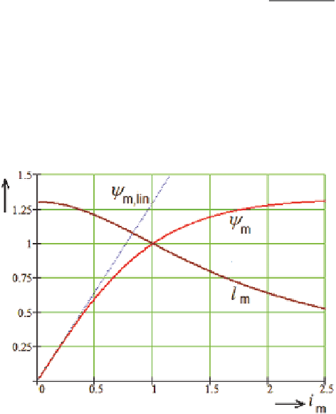
Figure 3.9 shows typical curves of the main field flux and inductance vs. magne-
tizing current in normalized representation.
Ψ
m
(
I
m
); according to
Fig. 3.9
Flux and inductance under main field saturation

Search WWH ::

Custom Search