Environmental Engineering Reference
In-Depth Information
3.2.3 Reactive Power Compensation
Asynchronous machines develop their flux by drawing reactive (magnetizing) power
via the terminals. In case of sinusoidal voltages and currents the power factor is:
=
P
1
P
1
P
1
2
+
Q
1
2
cos
ϕ
S
1
=
(3.14)
Here
Q
1
is the fundamental reactive power and
S
1
the apparent power. In grid
supply cos
can be improved (increased) by a compensation device. In case of
stand-alone operation all the required reactive power must be supplied indepen-
dently.
In grid-supplied a.c. drives it is well known to compensate part of the inductive
reactive power by using capacitors parallel to the stator winding, to achieve a power
factor of 0
,
9
...
0
,
95. In a three-phase star-connected circuit, using a per-phase ca-
pacitance
C
, the reactive power is:
ϕ
U
1
2
Q
= 3
·
·
ω
1
C
(3.15)
A stepwise adjustable reactive power can be obtained by using capacitor banks.
To obtain a continually adjustable compensation, different concepts are applicable.
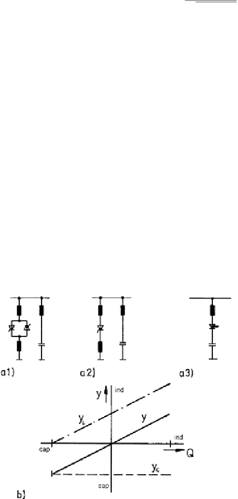
Figure 3.10a indicates the basic circuits.
1. phase-controlled a.c. inductive load and capacitor.
The voltage across the inductance is adjustable by phase-control, yielding ad-
justable reactive (inductive) power. Together with the set-value reactive (capaci-
tive) power of the capacitors the resultant reactive power is adjustable and may
be designed to cover both signs of reactive power (a1).
Fig. 3.10
Compensation device concepts (
a
) basic circuits; (
b
) admittance characteristics
Search WWH ::

Custom Search