Environmental Engineering Reference
In-Depth Information
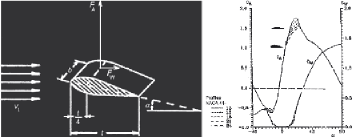
Fig. 2.4
Coefficients
c
A
(α) of lift and
c
W
(α) of drag over blade angle of specific profiles
direction, which is, according to Betz theory, 2/3 of the upstream wind velocity
v
1
.
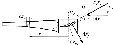
Both components added geometrically result in the speed
c
(
r
) which is directed
under angle
relative to the rotor plane, see Fig. 2.5. Consequently increments d
F
A
of lift force and d
F
W
of drag force are acting on the area increment (
t
α
d
r
) of the
blade. The force can be described by its components d
F
t
in tangential and d
F
a
in
axial direction:
·
d
F
t
d
F
a
=
2
c
2
t
d
r
c
A
sin
α
−
c
W
cos
α
(2.7)
c
A
cos
α
+
c
W
sin
α
Integrating for a given profile, the torque can be obtained from the tangential
forces, while the axial forces sum up to the drag force acting axially on the rotor.
At the tip of the blade,
r
=
R
, the tip speed is
u
(
R
)=
Ω
·
R
. Note that the wind
speed relative to the tip is:
c
(
R
)=
v
2
1 +
2
λ
An example of
c
p
(
λ
) and associated
c
T
(
λ
) curves for a rotor with fixed blade
angle designed for optimum tip-speed ratio
A
= 6
,
5 is shown in Fig. 2.6 [Gas07].
The basic characteristics of a wind rotor follow from the power coefficient c
P
(
λ
λ
)
and the torque coefficient c
T
(
λ
), (see 2.3, 2.4). Further a drag coefficient
c
S
is
Fig. 2.5
Wind speeds and forces acting on the blade

Search WWH ::

Custom Search