Environmental Engineering Reference
In-Depth Information
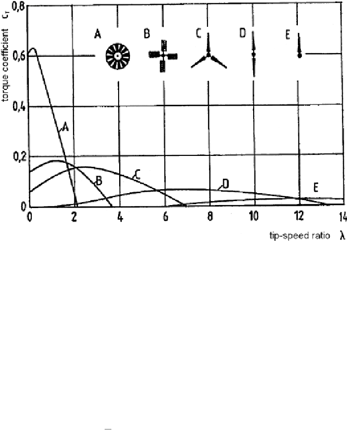
Fig. 2.3
Typical torque coefficients of different rotor with hotizontal shaft
2.2.2 Forces and Torque
The main rotor properties follow from lifting force and drag force of a blade as
described by aerofoil theory. Let an aerofoil element of depth
t
and width
b
be
subjected to a wind speed
v
1
, see Fig. 2.4. Dependent on the angle of attack
α
between wind direction and the blade profile cord, the lifting force
F
A
and drag
force
F
W
are:
·
2
v
1
·
F
A
=
c
A
(
α
)
t
·
b
normal to oncoming flow
·
2
v
1
·
F
W
=
c
W
(
α
)
t
·
b
in direction of oncoming flow
(2.6)
Note that these force components are directed perpendicular and parallel to the
oncoming wind, respectively. Coefficients
c
A
and
c
W
are characteristic for a given
blade profile; they depend on blade angle
. The example in Fig. 2.4 applies to real
unsymmetric profiles [Schm56]. For small values of
α
10
◦
) an almost
α
(0
≤
α
≤
proportional dependence of
c
A
=(5
,
1
...
5
,
8)
·
α
is observed, while
c
W
is compar-
atively small in the considered interval of
α
. The ratio
ε
=
c
A
/
c
W
is called the glide
ratio or lift/drag ratio.
When a wind rotor is rotating at an angular speed
Ω
, the circumferential speed of
Ω
·
each blade at radius
r
is
u
(
r
)=
r
. In the rotor plane the wind velocity is
v
2
in axial
Search WWH ::

Custom Search