Civil Engineering Reference
In-Depth Information
k
σ
cr
=
c
Dk
=
2
[4.11]
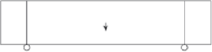
The IGNA of the beam section may move up to the compression area as
the tension area of the concrete beam is damaged and behaves in an
approximately plastic manner. The depth of the beam section (
2h
) and the
displacement of IGNA (the distance between the actual geometrical neutral
axis and the initial geometrical neutral axis
y
0
) are illustrated in Fig. 4.13.
The width of the beam section is
b
. During the loading process, the stress
pattern in the compression zone changes continuously. Based on the plane
section assumption, the relationship of stresses and strains may be described
as follows:
yy
hy
−
−
0
σ
=
σ
3
[4.12a]
t
0
hy
yh
+
−
0
σ
=
σ
[4.12b]
1
3
0
⎛
⎜
h
y
⎞
⎟
ε
=−
1
ε
[4.12c]
3
2
0
where
ε
3
are respectively the concrete strain at the top of the
beam (outer fi bre of the compression zone), the strain of the IGNA and
the strain of the extreme tension fi bre at the bottom, and
ε
1
,
ε
2
and
˜
3
are the
corresponding effective stresses at the top and bottom of the beam section,
respectively.
The resultant compression force
N
c
and the resultant tension force
N
t
in
the cross section of the beam may be expressed as follows:
σ
˜
1
,
σ
N
x
y
M
=
NL
/4
L
~
ε
1
σ
1
σ
1
ε
2
~
ε
3
σ
3
σ
3
4.13
Flexural damage of rectangular concrete beam.


Search WWH ::

Custom Search