Hardware Reference
In-Depth Information
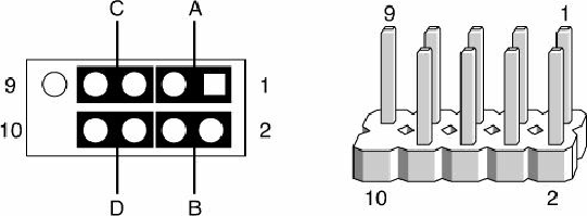
Some chassis provide a single 10-pin header connector for the front panel switch/LED connections,
but most provide individual 2-pin connectors for the various functions. If 2-pin connectors are used,
they are connected as shown in
Figure 4.32
.
Note that you can easily replace the multiple 2-pin
connectors with a single 10-pin connector; some chassis even include an adapter for this purpose.
Figure 4.32. Standard front panel switch/LED connections using 2-pin connectors.
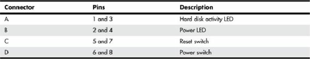
4.38
.
Table 4.38. Front Panel Switch/LED Connections Using Multiple Connectors
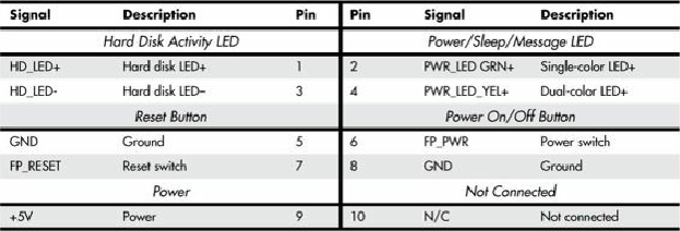
A chassis can use either a single-color or dual-color LED for the Power LED function. A dual-color
LED can provide more information about the various power and message states the system might be
in, including power on/off, sleep, and message-waiting indications.
Table 4.39
shows the possible
states and meanings for both single- and dual-color power LEDs.
Table 4.39. Power LED Indications