Environmental Engineering Reference
In-Depth Information
1
1
P2
0.1
0.1
P2
P3
0.9
0.9
P3
P5
P5
0.05
0.05
0.8
0.8
P4
P4
P1
P1
0.7
0.7
0
0
2350
2450
2550
2250
2350
2450
0.6
0.6
0.5
0.5
0.4
0.4
0.3
0.3
0.2
0.2
P5
P5
0.1
0.1
P1
P4
P1
P4
0
0
1400
1600
1800
2000
2200
2400
2600
1400
1600
1800
2000
2200
2400
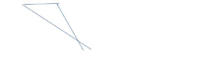
Static Pressure (Pa)
Static Pressure (Pa)
Fig. 14 Static pressure at pressure taps P1
-
P5att = 400 ms (left) and 800 ms (right) in the
complete CD-CLC configuration
4.3 Cold Flow Simulation of Modi
ed Complete CD-CLC
System Using Spouted Fluidized Bed Fuel Reactor
The formation of new gas bubbles and continuous solid recirculation from the loop
seal to the fuel reactor are the two key factors for successful CD-CLC operation,
which were not satisfactorily achieved in the simulation results for the CD-CLC
con
guration
are necessary to address these two factors for improved performance. We introduce
three modi
guration considered in the previous section; modi
cations to the con
guration as shown in Fig.
15
. First, a chute
is added to the bottom of the fuel reactor. The dimensions of the central jet injection
nozzle remain unchanged, while the two side panels of the chute are at about 60
°
from the horizontal. Second, the loop seal and solid recirculation duct are elevated
by 20 mm. Finally, the height of the fuel reactor and downcomer is reduced by
250 mm. The rationale behind each of these modi
cations to the CD-CLC con
cations is discussed below.
The addition of the chute at the bottom is to induce gravity-driven particle
circulation into the central jet. Such a consideration originates from the critical
angle of repose (
) for particulate materials (Lee and Herrmann
1993
; Miller and
Byrne
1966
; Samadani and Kudrolli
2001
; van Burkalow
1945
; Zhou et al.
2001
),
which is de
θ
ned as the steepest angle of descent of the slope relative to the hori-
zontal plane when the particulate material on the slope face is on the verge of
sliding. Due to the existence of
, a dead zone in which particles are stagnant can be
θ
identi
fluidized bed as discussed by Takeuchi et al. (
2004
,
2005
)
and as evident from Fig.
13
. The poor recirculation of solid particles observed in
Fig.
13
is thus also partially explained by the fact that the recirculation duct was
connected to the bottom of the fuel reactor, i.e., to the dead zone. Since the particles
in the dead zone are stationary regardless of ambient gas
ed in a spouted
fl
flow, high pressure is
always present at the bottom of the fuel reactor, impeding the transport of the
particles pneumatically from the loop seal. Introducing the bottom chute eliminates
the dead zone, relieving the pressure in the fuel reactor for better recirculation of
particles. Similarly, elevating the loop seal and recirculation duct serves to reduce
the pressure at the connecting point of the recirculation duct into fuel reactor for
further improved particle recirculation. Lastly, the reduction in height of the fuel
fl


Search WWH ::

Custom Search