Biomedical Engineering Reference
In-Depth Information
(a)
(b)
Sampling aerosol
Sampling hood
Abrasion wheel
Sample
(c)
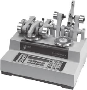
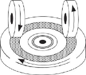
FIGURE 12.6
(a) Taber Abraser. (b) Abrasion scheme of a Taber Abraser with test piece
(sample), abraded area, abrasion wheels, and the direction of rotation (marked with arrows),
and (c) schematic illustration of the modified Taber Abraser with sampling hood. ((a) Courtesy
of Taber Industries, USA. (c) Reprinted from
Aerosol. Sci
., 40, Vorbau, M. et al., Methods for
the characterization of the abrasion induced nanoparticles release into air from surface coat-
ings, 209-217, Copyright 2009, with permission from Elsevier.)
Enclosure chamber
Flow
meter
Sampling
line
Particle sampling
Sample
Taber
SNPS
Sample
Abrasion wheel
Clean air
(a)
(b)
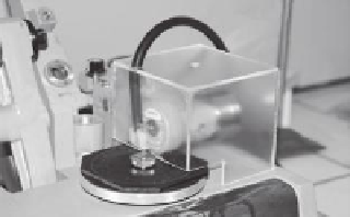
FIGURE 12.7
Abrasion area of the Taber Abraser with the enclosure chamber from
Schlagenhauf et al. (2012) (a) and (b) principle test setup of a Taber Abraser to test nanopar-
ticle release. (Reprinted with permission from Guiot, A. et al., Measurement of nanoparticlere-
moval by abrasion. J Phys Conf Ser 170:012014. Copyright 2009 American Chemical Society.
Reprinted with permission from Schlagenhauf, L. et al., Release of carbon nanotubes from an
epoxy-based nanocomposite during an abrasion process.
Environ Sci Technol
46: 7366-7372.
Copyright 2012 American Chemical Society.)


Search WWH ::

Custom Search