2.2
2.2.1
Why digital technology simplifies signal processing
2.2.1.1
Common signal-processing operations
Signal-processing circuits apply a number of operations to the input signal(s):
• Sum.
• Difference.
• Multiplication (modulation of one signal by another).
• Differentiation (derivative).
• Integration.
• Frequency analysis.
• Frequency filtering.
• Delay.
It is obvious that the sum and difference operations are easy to perform with discrete time digitized signals, but they are also very easy to perform with analog systems. On the other hand, all other operations are much simpler to perform with digital systems.
The differentiation of a signal f (t), for instance, typically requires an inductance or a capacitor in an analogue system, both of which are very difficult to miniaturize. But
![tmp42-10_thumb[1] tmp42-10_thumb[1]](http://lh4.ggpht.com/_X6JnoL0U4BY/S4PKhvK6GlI/AAAAAAAATjk/eY7xkmkDyk0/tmp4210_thumb1_thumb.png?imgmax=800)
Similarly, the primitive F of a function f can be approximated on the digitized version of f summing all samples f(k) * T (Figure 2.10).
All audio filters realizable using discrete components can today be emulated digitally. With the ever-increasing frequency of modern processors, even radio frequency signals are now accessible to digital signal processing.
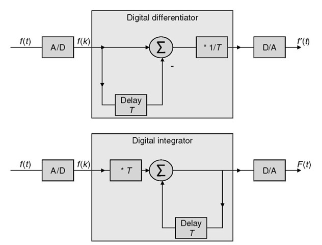
Figure 2.10 Differentiation and integration with digital filters.
The tools presented below allow engineers to synthesize digital filters that implement a desired behavior or predict the behavior of a given digital filter.
2.2.1.2
Example of an integro-differential filter
Most filters can be represented as a set of integro-differential equations between input signals and output signals. For instance, in the following circuit (Figure 2.11) the input voltage and the resulting current are linked by the following equation:

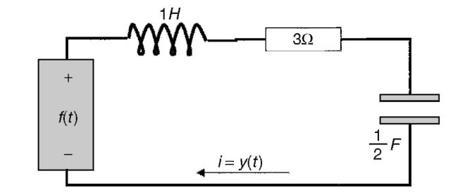
Figure 2.11 Simple circuit that can be modeled by an integro-differential equation.
or if D is the symbol of the differentiation operator:
(D2 + 3D + 2)y(t) = Df(t)
The D2 + 3D + 2 part is also called the characteristic polynomial of the system. The solutions of x2 + 3x + 2 = 0 also give the value of the exponents of the pure exponential solutions of the equation when the input signal f (t) is null (‘zero input solution’). The reader can check that — land —2 are the roots of x2 + 3x + 2and that e—t and e— 2t are solutions of the y”(t) + 3y’(f) + 2y(t) = 0 equation. The solutions are complex in general, but should occur as pairs of conjugates for real systems (otherwise the coefficients of the characteristic polynomial are not real), so that real solutions can be obtained by combining exponentials obtained from conjugate roots. Repeated roots r yield solutions of the form tl—1ert if the root is repeated i times.
Let’s assume a sampling period of 1. The system equation can readily be transformed in a discrete time form (linear difference equation):
![tmp42-14_thumb[1] tmp42-14_thumb[1]](http://lh3.ggpht.com/_X6JnoL0U4BY/S4PKxjE57mI/AAAAAAAATkE/mSm2J_7V-Ko/tmp4214_thumb1_thumb.png?imgmax=800)
2.2.2
The Z transform and the transfer function
2.2.2.1
Definition
![tmp42-15_thumb[1] tmp42-15_thumb[1]](http://lh3.ggpht.com/_X6JnoL0U4BY/S4PKzfBqvSI/AAAAAAAATkM/Rou25vlm8XI/tmp4215_thumb1_thumb.png?imgmax=800)
(the integral is performed on a closed path within the convergence domain in the complex plane).
Table 2.4 Short extract of a Z transform table
![tmp42-16_thumb[1] tmp42-16_thumb[1]](http://lh5.ggpht.com/_X6JnoL0U4BY/S4PM9Wj42rI/AAAAAAAATkY/H3GZHfNiIuw/tmp4216_thumb1_thumb.png?imgmax=800)
The Z transform is a linear operator: any linear combination of functions is transformed into the same linear combination of their respective Z transforms.
In practice these complex calculations are simplified by the use of transform tables that cover most useful signal forms. A small extract is presented in Table 2.4.
2.2.2.2
Properties
The Z transform has important properties. If u(k) designates the step function (u(k) = 0, k< 0; u(k) = 1, k > 0) and F(z) is the Z transform of f (k)u(k), then:
![tmp42-17_thumb[1] tmp42-17_thumb[1]](http://lh6.ggpht.com/_X6JnoL0U4BY/S4PNFy83VmI/AAAAAAAATkk/VirPRwtdLUQ/tmp4217_thumb1_thumb.png?imgmax=800)
The Z transform is a powerful tool to solve linear difference equations with constant coefficients.
2.2.2.3
Notation
Note that the Z transform of a unit delay is ’1/z’andthez transform of a unit advance is ‘ z’. Both expressions will appear in diagrams in the following subsections.
In the following subsections, some figures will show boxes with an input, one or more outputs, adders, and multipliers, similar to Figure 2.12.
The meaning is the following: the sampled signal E is filtered by H1(z) resulting in response signal Y. Then, signal T is obtained by subtracting the previous output S (one sample delay) from signal Y. Finally, signal S is obtained by filtering signal T by filter H2(z).

Figure 2.12 Typical digital filter representation.
2.2.2.4
Using the Z transform. Properties of the transfer function
With T = i in the discrete difference equation above, for instance, we have:
![tmp42-19_thumb[1] tmp42-19_thumb[1]](http://lh3.ggpht.com/_X6JnoL0U4BY/S4PNM_oU_mI/AAAAAAAATk0/-ecYBEBcjcw/tmp4219_thumb1_thumb.png?imgmax=800)
![tmp42-20_thumb[1] tmp42-20_thumb[1]](http://lh5.ggpht.com/_X6JnoL0U4BY/S4PfKBtthdI/AAAAAAAATmI/kK7HQMnbFjg/tmp4220_thumb1_thumb.png?imgmax=800)
When considering the equation using the advance operator form (16E2 — 20E + 6)y(k) = (E — 1)f(k), the numerator coefficients are the same as the coefficients for f(k) and the denominator coefficients are the same as the coefficients for y(k).
This is generally the case: the transfer function H(z) can be obtained very simply from the coefficients of the difference equation using the advance operator (which will be shown in Subsection 2.2.2.5). This is one of the reasons the Z transform is so useful, even without complex calculations!
Another interesting property is that the Z transform of the impulse response of the system h(k) is H(z). The impulse function 5(0) is the input signal with e(0) = 1and e(k) = 0 everywhere else. The impulse response is the response s(k) of the system when the input is 5(0). The proof goes beyond the scope of this topic.
2.2.2.5
Application for FIR and IIR filters
The impulse response h(k) of a linear, time-invariant, discrete time filter determines its response to any signal:
• Because of linearity, the response to an impulse of amplitude a is ah(k).
• Because of time invariance, the response to a delayed impulse 5(k — x) is h(k — x).
Any input signal e(k) can be decomposed into a sum of delayed impulses, and because of the linearity of the filter we can calculate the response. Each impulse e(x) creates a response e(x)h(k — x),where k is the discrete time variable. The response s(n) at instant n is e(x)h(n — x). The sum of all the response components at instant n for all e(x) is:

This is a convolution of e and h in the discrete time domain. This relation is usually rewritten by taking m = n — x:

For a physically realizable system (which cannot guess a future input signal and therefore cannot react to 5(0) before time 0), we must have h(x) = 0for x< 0. Physically realizable systems are also called causal systems.
Filters that only have a finite impulse response are called finite impulse response (FIR) filters. The equation for an FIR filter is:
![tmp42-23_thumb[2] tmp42-23_thumb[2]](http://lh4.ggpht.com/_X6JnoL0U4BY/S4PfOfzn8xI/AAAAAAAATmg/HVD8CK4mgAQ/tmp4223_thumb2_thumb.png?imgmax=800)
where the h(k) for k = 0to N are constants that characterize the system. In voice-coding filters these constants are sometimes dynamically adapted to the signal, but with a timescale that is much lower than the variance of the signal itself: they are in fact a succession of FIR filters with varying coefficients.
Filters that have an infinite impulse response are called infinite impulse response (IIR) filters. In many filters the response is infinite because recursivity has been introduced in the equation of the filter. The equation for a recursive IIR filter is:
![tmp42-24_thumb[1] tmp42-24_thumb[1]](http://lh3.ggpht.com/_X6JnoL0U4BY/S4PfPyp06RI/AAAAAAAATmo/n-ZBv4t0i1I/tmp4224_thumb1_thumb.png?imgmax=800)
Note that we have introduced the past values of the output (s(n — k)) in the formula and that the values a(k) and b(k) characterize the system. When we compute the Z transform of the time domain equation of an IIR filter:
![tmp42-25_thumb[1] tmp42-25_thumb[1]](http://lh3.ggpht.com/_X6JnoL0U4BY/S4PfSUiiIWI/AAAAAAAATmw/brMg5w3MOn4/tmp4225_thumb1_thumb.png?imgmax=800)
We can also calculate the output-to-input ratio in the Z domain:
![tmp42-26_thumb[3] tmp42-26_thumb[3]](http://lh3.ggpht.com/_X6JnoL0U4BY/S4PfTwIcRII/AAAAAAAATm4/6HNCWx80Gmw/tmp4226_thumb3_thumb.png?imgmax=800)
We see that the transfer function in the Z domain has an immediate expression from the coefficients of the filter equation.
2.2.2.6
System realization
A given transfer function H(z) is easily realizable by a discrete time filter. For instance, if:
![tmp42-27_thumb[1] tmp42-27_thumb[1]](http://lh5.ggpht.com/_X6JnoL0U4BY/S4PfWPylbmI/AAAAAAAATnA/Q-lFBaY_QdY/tmp4227_thumb1_thumb.png?imgmax=800)
which is realized by a system like that in Figure 2.13.
A second step is to obtain Y(z) by a linear combination of the z’X(z), as in Figure 2.14.

Figure 2.13 Realization of H(z) denominator.
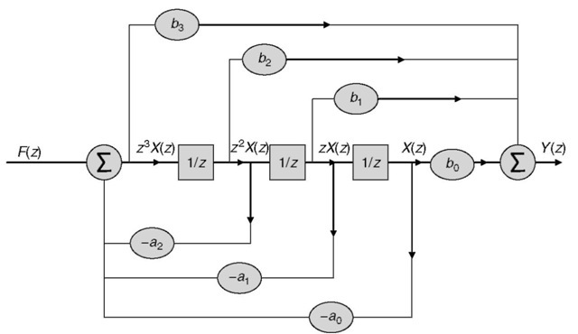
Figure 2.14 Full realization of H(z).
2.2.2.7
Realization of frequency filters
The fact the transfer function H(z) = Y(z)/F(z) is also the Z transform of the impulse response makes it very useful to determine the frequency response of a discrete time filter. If h(k) is the impulse response of a system, the system response y(k) to input zk is:
![tmp42-30_thumb[1] tmp42-30_thumb[1]](http://lh6.ggpht.com/_X6JnoL0U4BY/S4Pfa7bnZ3I/AAAAAAAATnY/qYJ1gSAeIWE/tmp4230_thumb1_thumb.png?imgmax=800)
where H(z) is the Z transform of the filter impulse response and the transfer function as well. A sampled continuous time sinusoid cos(cot) is of the form cos(&>Tk) = Re(ejwTk) where T is the sampling period. A sample sinusoid respecting the Nyquist limit must have co< n/T .If wetake z = ejwT, the above result tells us that the frequency response of the filter to the discrete time sinusoid is:
![tmp42-31_thumb[2] tmp42-31_thumb[2]](http://lh4.ggpht.com/_X6JnoL0U4BY/S4PfcE9AVaI/AAAAAAAATng/cJxxNEagk84/tmp4231_thumb2_thumb.png?imgmax=800)
Therefore, we can predict the frequency response of a system by studying H(ejmT). H(z) can be rewritten as a function of its zeros zi and its poles pt:
![tmp42-32_thumb[1] tmp42-32_thumb[1]](http://lh4.ggpht.com/_X6JnoL0U4BY/S4PfeAcgYWI/AAAAAAAATno/jwg_8jUgj7o/tmp4232_thumb1_thumb.png?imgmax=800)
for stable systems the poles must be inside the unit complex circle, and for physically realizable systems we must have n<m and poles and zeros should occur as pairs of conjugates.
A graphical representation of the transfer function (Figure 2.15) for two zeros and two poles makes it simple to understand how H behaves as a function of &>.
The amplitude of the original sinusoid is multiplied by:
![tmp42-33_thumb[2] tmp42-33_thumb[2]](http://lh5.ggpht.com/_X6JnoL0U4BY/S4PffesshZI/AAAAAAAATnw/xHbtUf46xDA/tmp4233_thumb2_thumb.png?imgmax=800)
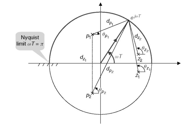
Figure 2.15 Graphical interpretation of the transfer function.
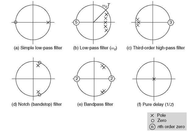
Figure 2.16 Graphical representation of common filters.
and the phase of the original sinusoid is changed by the angle:
![tmp42-36_thumb[1] tmp42-36_thumb[1]](http://lh6.ggpht.com/_X6JnoL0U4BY/S4Pf_sdEnSI/AAAAAAAAToI/ETRF1-Y0uMk/tmp4236_thumb1_thumb.png?imgmax=800)
Frequency filters can be realized by placing poles near the frequencies that need to be amplified and zeros near the frequencies that need to be attenuated. Figure 2.16 gives a few examples.
In a simple low-pass filter (case A), a pole is placed near point 1 (it needs to be inside the unit circle for a stable system), and a zero at point —1 (zeros can be anywhere). The cut-off frequency for such a filter is at oT = n/2.
In order to ensure that the gain is sustained on a specific band [0 — oc ], more poles must be accumulated near the unit circle in the band where the gain must be close to unity (case B).
The principle of the high-pass filter (C) is similar, but the roles of the zeros and poles are inverted. A higher order filter will have a sharper transition at the cut-off frequency and therefore will better approach an ideal filter. Note that a realizable system (where the future is not known in advance) requires more poles than zeroes or an equal number of poles and zeros.
A notch (bandstop) filter (D) is obtained by placing a zero at the frequency that must be blocked. A zero must be placed at the conjugate position for a realizable system (all the coefficients of the polynomials of the transfer function fraction must be real). Poles can be placed close to the zeros to quickly recover unity gain on both sides of the blocked frequency.
A bandpass filter (E), can be obtained by enhancing the frequencies in the transmission band with poles and attenuating frequencies outside this band by placing zeros at points 1 and — 1.
Note that a pole placed at the origin (F) does not change the amplitude response of the filter, and therefore a pole can always be added there to obtain a physically realizable system (more poles than zeros). A filter with a single pole at the origin is in fact a pure delay of period T (linear phase response of —oT). This is logical: filters cannot be realized if they need to know a future sample •• • and can be made realizable by delaying the response of the filter in order to accumulate the required sample before computing the response. Similarly a zero at the origin is a pure advance of T.
The ease with which arbitrary digital filters can be realized using the results of this section and the method of the previous section sharply contrasts with the complexity of analog filters, especially for high-order filters. This is the reason discrete time signal processing has become so prevalent.
2.2.3
Linear prediction for speech-coding schemes
2.2.3.1
Linear prediction
Linear prediction is used intensively in speech-coding schemes; it uses a linear combination of previous samples to construct a predicted value that attempts to approach the next input sample:

gives the predicted value at time n.
The coefficients ak must be chosen to approach the s(n)value. If sp (n) is indeed similar to s(n), then the error signal e(n) = s(n) — sp(n) can be viewed as a residual signal resembling a white noise.
With this remark, we can decompose the issue of transmitting speech information (the waveform) into two separate problems:
• The transmission of the set of coefficients ak (or some coded representations).
• The transmission of information related to the error signal e(n)
Ideally, if e(n) was white noise, then only its power should be sent. In reality, e(n) is not white noise and the challenge to speech coder experts is to model this error signal correctly and to transmit it with a minimal number of bits.
The ak coefficients are called linear prediction coefficients (LPCs) and p is the order of the model. Each LPC vocoder uses its own methods for computing the optimal ak coefficients. One common method is to compute the ak that minimize the quadratic error on the samples to predict, which leads to a linear system (the equation of Yule-Walker) that can be solved using the Levinson-Shur method. Usually, these coefficients are computed on a frame basis of 10-30 ms during which the speech spectrum can be considered as stationary.
2.2.3.2
The LPC modeling filter
In the previous subsection, we showed that a speech signal s could be approached by a linearly predicted signal sp obtainedbyanLPC filter L. Another way to view this is to say that the speech signal, filtered by the (1 — L) filter, is a residual error signal ideally resembling white noise.
At this point, it is interesting to wonder whether the inverse filter can approach the original speech spectrum by filtering an input composed of white noise. To find the expression of the inverse filter, we can use the previous equation, replacing sp(n) by its expression as a function of s:
![tmp42-38_thumb[1] tmp42-38_thumb[1]](http://lh5.ggpht.com/_X6JnoL0U4BY/S4PgIm-7CqI/AAAAAAAAToY/32b38S-aA6c/tmp4238_thumb1_thumb.png?imgmax=800)
is called the LPC modeling filter. It is an all pole filter (no zero) that models the source (speech). If we want to evaluate the residual error signal we only need to filter the speech signal (s(n)) by the filter A(z) because we have E(z) = S(z)A(z). A(z) is often called
the LPC analysis filter (giving the residual signal) and H(z) = 1/A(z) the LPC synthesis filter (giving the speech signal from the residual signal). These concepts are intensively used in the low-bitrate speech coder schemes discussed in the following section.
Note that we are only trying to approach the frequency spectrum of the original speech signal, not the exact time representation: this is because human hearing is not sensitive to the exact phase or time representation of a signal, but only to its frequency components.
