2.1
A primer on digital signal processing
2.1.1
Introduction
At the beginning of the 20th century, all devices performing some form of signal processing (recording, playback, voice or video transmission) were still using analogue technology (i.e., media information was represented as a continuously variable physical signal). It could be the depth of a groove on a disk, the current flowing through a variable resistance microphone, or the voltage between the wires of a transmission line. In the 1960s, the PCM (pulse code modulation) of audio began to be used in telecom switching equipment. Since 1980 the spectacular performance advances of computers and processors led to an ever-increasing use of digital signal processing.
Today speech signals sampled at 8 kHz can be correctly encoded and transmitted with an average of 1 bit per sample (8 kbit/s) and generic audio signals with 2 bits per sample. Speech coders leverage the redundancies within the speech signal and the properties (the weaknesses) of human ears to reduce the bitrate. Speech coding can be very efficient because speech signals have an underlying vocal tract production model; this is not the case for most audio signals, such as music.
This topic will first explain in more detail what a ‘digital’ signal is and how it can be obtained from a fundamentally analogue physical input that is a continuously variable function of time. We will introduce the concepts of sampling, quantization, and transmitted bandwidth. These concepts will be used to understand the basic speech-coding schemes used today for telephony networks: the ITU-T A-law and |i-law encodings at 64 kbits per second (G.711).
At this point the reader may wonder why there is such a rush toward fully digital signal processing. There are multiple reasons, but the key argument is that all the signal transformations that previously required discrete components (such as bandpass filters, delay lines, etc.) can now be replaced by pure mathematical algorithms applied to the digitized signal. With the power of today’s processors, this results in a spectacular gain in the size of digital-processing equipment and the range of operations that can be applied to a given signal (e.g., acoustic echo cancellation really becomes possible only with digital processing). In order to understand the power of fully digital signal processing, we will introduce the ‘Z transform’, the fundamental tool behind most signal-processing algorithms.
We will then introduce the key algorithms used by most voice coders:
• Adaptive quantizers.
• Differential (and predictive …) quantization.
• Linear prediction of signal.
• Long-term prediction for speech signal.
• Vector quantization.
• Entropy coding.
There are two major classes of voice coders, which use the fundamental speech analysis tools in different ways:
• Waveform coders.
• Analysis by synthesis voice coders.
After describing the generic implementation of each category, the detailed properties of the most well known standardized voice coders will be presented. We will conclude this topic by a presentation of speech quality assessment methods.
2.1.2
Sampling and quantization
Analog-to-digital conversion is the process used to represent an infinite precision quantity, originally in a time-varying analog form (such as an electrical signal produced by a microphone), by a finite set of numbers at a fixed sample rate, each sample representing the state of the original quantity at a specific instant. Analog-to-digital conversion is mandatory in order to allow computer-based signal analysis, since computers can only process numbers.
Analog-to-digital conversion is characterized by:
• The rate of sampling (i.e., how often the continuously variable quantity is measured).
• The quantization method (i.e., the number of discrete values that are used to express the measurement (typically a certain number of bits), and how these values are distributed
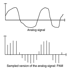
Figure 2.1 Pulse amplitude modulation.
(linearly on the measurement scale, or with certain portions of the measurement scale using a more precise scale than others)).
Mathematically, the sampling process can be defined as the result of the multiplication of an infinite periodical pulse train of amplitude 1 (with a period corresponding to the sampling period), by the original continuous-time signal to be sampled. This leads to the PAM (pulse amplitude modulation) discrete time representation of the signal (Figure 2.1).
From the PAM signal, it is possible to regenerate a continuous time signal. This is required each time the result of the signal-processing algorithm needs to be played back. For instance, a simple discrete-to-continuous (D/C) converter could generate linear ramps linking each pulse value, then filter out the high frequencies generated by the discontinuities.
Analog-to-digital conversion looses some information contained in the original signal, which can never be recovered (this is obvious in Figure 2.2). It is very important to choose the sample rate and the quantization scale appropriately, as this directly influences the quality of the output of the signal-processing algorithm [A2, B1, B2].

Figure 2.2 Reconstruction of a continuous signal from a discrete signal.
2.1.3
The sampling theorem
The sampling theorem states that in order to process a continuous time signal with frequency components comprised between 0 and Fmax, the sampling rate should be at least 2 * Fmax. Intuitively, it can be understood by looking at the quantization of a pure sinusoid. In Figure 2.3 the original signal of frequency 1.1 is sampled at frequency 1. The resulting PAM signal is identical to the sampling result at frequency 1 of a signal at frequency 0.1. This is the aliasing phenomenon.
In fact if T is the sampling period (radial frequency Qr = 2n/T):
• All sinusoids of frequency cor + mQr will have the same PAM representation as the sinusoid of frequency cor,since cos((&>r + m(2n/T))t) is sampled as
cos((&v + m(2n/T)kT) = cos((corkT + mk2n) = cos(corkT)
• The sinusoids of frequencies Qr/2 + cor and Qr/2 — cor have the same PAM representation because
cos((£2r/2 ± cor)kT) = cos(nk ± eorkT) = cos(nk) cos(corkT) ^ sin(nk) sin(&>rkT) = cos(nk) cos(&>rkT)
This is illustrated on Figure 2.4.
The conclusion is that there is one-to-one mapping between a sinusoid and its PAM representation sampled at frequency Q only if sinusoids are restricted to the [0, £2/2] range. This also applies to any signal composed of mixed sinusoids: the signal should not
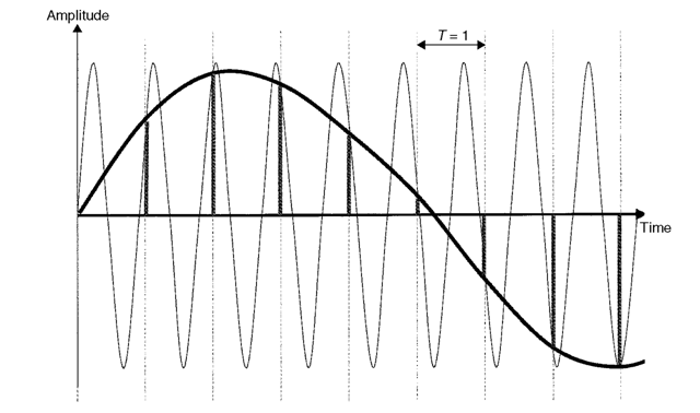
Figure 2.3 Aliasing of frequency 1.1, sampled at frequency 1, wrapped into frequency 0.1.
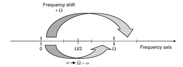
Figure 2.4 The different types of frequency aliasing.
have any frequency component outside the [0, £2/2] range. This is known as the Nyquist theorem, and £2 = 2m is called the Nyquist rate (the minimal required sampling rate for a signal with frequency components in the [0, m] range).
The Nyquist (or Shannon) theorem also proves that it is possible to exactly recover the original continuous signal from the PAM representation, if the sampling rate is at or above the Nyquist rate. It can be shown that the frequency spectrum (Fourier transform) of a PAM signal with sampling frequency Fs is similar to the frequency spectrum of the original signal, repeated periodically with a period of Fs and with a scaling factor.
From Figure 2.5 it appears that the original signal spectrum can be recovered by applying an ideal low-pass filter with a cutting frequency of Fs/2 to the PAM signal. The unique condition to correctly recover the original analog spectrum is that there is no frequency wrapping in the infinite PAM spectrum. The only way to achieve this
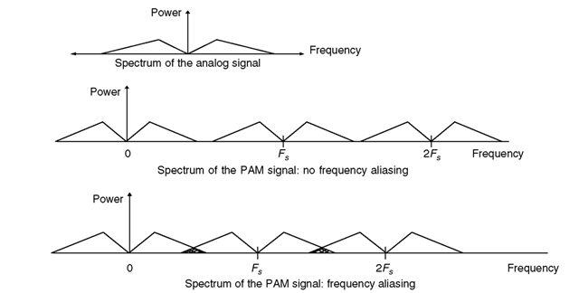
Figure 2.5 The Nyquist rate and frequency wrapping.
is for the bandwidth of the original analog signal to be strictly limited to the frequency band [0, Fs/2]. Figure 2.5 shows an ideal situation and a frequency-wrapping situation; in the case of frequency wrapping, the recovered signal is spoiled by frequency aliasing.
The spectrum of real physical signals (such as the electrical signal generated by a microphone) do not have a well-defined frequency limit. Therefore, before the sampling process, it is necessary to cut off any frequency component beyond the Nyquist frequency by using an ‘anti-aliasing’ analog filter. In order to avoid this discrete component (it is not obvious to approximate an ideal low-pass filter with analog technology), modern oversampled noise-shaping analog-to-digital converters (also called sigma delta coders) use a very high-sampling frequency (the input signal is supposed not to have any very high-frequency component) but internally apply digital decimation (subsampling) filters which perform the anti-aliasing task before the sampling rate is reduced.
In the digital-to-analog chain, the reconstruction filter is responsible for transforming the discrete digital signal into a continuous time signal.
The value of the sampling frequency not only determines the transmitted signal bandwidth but also impacts the amount of information to be transmitted: for instance, wideband, high-quality audio signals must be sampled at high frequencies, but this generates far more information than the regular 8,000-Hz sampling frequency used in the telephone network.
2.1.4
Quantization
With the sampling process discussed in the previous paragraph, we are not yet in the digital world. The PAM signal is essentially an analog signal because the amplitude of each pulse is still a continuous value that we have not attempted to measure with a number. In fact we have lost only part of the information so far (the part of the sampled signal above one-half of the sampling frequency). We will lose even more information when we measure the amplitude of each pulse.
Let’s imagine that a folding rule is used to measure the amplitude of the PAM signal. Depending of the graduation or precision of the scale, the number that represents the PAM signal can be more or less precise … but it will never be exact. The PAM signal can be represented by the digital signal with pulses corresponding to the measured values, plus a PAM signal with pulses representing the errors of the quantization process. The signal encoding in which each analog sample of the PAM signal is encoded in a binary code word is called a PCM (pulse code modulation) representation of the signal. The analog-to-digital conversion is called quantization.
With a more precise quantization process, we minimize the amplitude of the noise, but we cannot avoid introducing some noise in the quantization process (quantization noise). Once quantization noise is introduced in a speech or audio transmission chain, there is no chance to improve the quality by any means. This has important consequences: for instance, it is impossible to design a digital echo canceler working on a PCM signal with a signal-to-echo ratio above the PCM signal’s signal-to-noise ratio.
Therefore there are two sources of loss of information when preparing a signal for digital processing:
• The loss of high-frequency components.
• Quantization noise.
The two must be properly balanced in any analog-to-digital (A/D) converter as both influence the volume of information that is generated: it would be meaningless to encode with a 24-bit accuracy a speech signal which is intentionally frequency-limited to the 300-3,400-Hz band; the limitation in frequency is much more perceptible than the ‘gain’ in precision brought by the 24 bits of the A/D chain.
If uniform quantization is applied (‘uniform’ means that the scale of our ‘folding rule’ is linear) the power of the quantization noise can be easily derived. All the step sizes of the quantizer have the same width D; therefore, the error amplitude spans between — D/2 to +D/2 and it can be shown [B1] that the power of this error is:
![tmp42-6_thumb[2] tmp42-6_thumb[2]](http://lh4.ggpht.com/_X6JnoL0U4BY/S4PJn0blUwI/AAAAAAAATjE/Vg1kzscBSOc/tmp426_thumb2_thumb.png?imgmax=800)
For a uniform quantizer using N bits (N is generally a power of 2) the maximum signal-to-noise ratio (SNR) achievable in decibels is given by:
SNR(dB) = 6.02N — 1.73
For example, a CD player uses a 16-bit linear quantizer and the maximum achievable SNR is 94.6 dB. This impressive figure hides some problems: the maximum value is obtained for a signal having the maximum amplitude (e.g., a sinusoid going from —32,768 to +32,767). In fact, the SNR is directly proportional to the power of the signal: the curve representing the SNR against the input power of the signal is a straight line. If the power of the input signal is reduced by 10 dB, the SNR is also reduced by 10 dB. For very low-power sequences of music, some experts (golden ears) can be disturbed by the granularity of the sound reproduced by a CD player and prefer the sound of an old vinyl disk.
Because of this problem, the telecom industry generally uses quantizers with a constant SNR ratio regardless of the power of the input signal. This requires nonlinear quantizers (Figure 2.6).
As previously stated, the sampling frequency and the number of bits used in the quantization process both impact the quality of the digitized signal and the resulting information rate: some compromises need to be made. Table 2.1 [A2] gives an overview of the most common set of parameters for transmitting speech and audio signals (assuming a linear quantizer).
Even a relatively low-quality telephone conversation results in a bitrate around 100 kbit/s after A/D conversion. This explains why so much work has been done to reduce this bitrate while preserving the original quality of the digitized signal. Even the well-known A-law or |i-law PCM G.711 coding schemes at 64 kbit/s, used worldwide in all digital-switching machines and in many digital transmission systems, can be viewed as a speech coder.
![Example of a nonlinear quantizer. Any value belonging to [x - q,/2, x, + q/2] is quantized and converted in x,. The noise value spans in [—q/2, +q//2]. Example of a nonlinear quantizer. Any value belonging to [x - q,/2, x, + q/2] is quantized and converted in x,. The noise value spans in [—q/2, +q//2].](http://lh4.ggpht.com/_X6JnoL0U4BY/S4PJqmlCZ2I/AAAAAAAATjM/bivR5_C5zS4/tmp427_thumb1_thumb.png?imgmax=800)
Figure 2.6 Example of a nonlinear quantizer. Any value belonging to [x - q,/2, x, + q/2] is quantized and converted in x,. The noise value spans in [—q/2, +q//2].
Table 2.1 Common settings for analog-to-digital conversion of audio signals
| Type | Transmitted bandwidth (Hz) | Sampling frequency (kHz) | Number of bits in A/D and D/A converters |
Bitrate in kbit/s | Main applications |
| Telephone speech | 300-3,400 | 8 | 12 or 13 | 96 or 104 | PSTN, ISDN networks, digital cellular |
| Wide-band speech (and audio) | 50-7,000 | 16 | 14 or 15 | 224 or 240 | Video and audio conferencing, FM radio |
| High-quality speech and audio | 30-15,000 | 32 | 16 | 512 | Digital sound for analog TV (NICAM) |
| 20-20,000 | 44.1 | 16 | 706 | audio CD player | |
| 10-22,000 | 48 | Up to 24 | 1,152 | Professional audio |
2.1.5
ITU G.711 A-law or p>law, a basic coder at 64 kbit/s
A linear quantizer is not usually optimal. It can be mathematically demonstrated that if the probability density function (PDF) of the input signal is known, an optimal
quantizer [B1, B2] can be computed which leads to a maximal SNR for this signal. The resulting quantizer is not linear for most signals. Of course, the main issue is to know the PDF of a given signal; for random speech and audio signal, this is a very difficult task as it may depend on multiple factors (language, speaker, loudness, etc.).
Another approach to finding an optimal quantizer is to look for a quantizer scale which yields an SNR independent of the level of the signal. It can be shown that this requires a logarithmic scale: the step size of the quantizer is doubled each time the input level is doubled. This process is called companding (compress and expanding): compared with the PAM signal, the digital PCM representation of the signal is ‘compressed’ by the logarithmic scale, and it is necessary to expand each PCM sample to obtain the PAM signal back (with quantization noise).
The ITU telephony experts also noted that the 12-13-bit precision of the linear quantizers discussed above were only useful for very weak signals, and such a precision was not necessary at higher levels. Therefore, a step size equivalent to the step size of a 12-bit linear quantizer would be needed only at the beginning of the logarithmic scale.
The ITU G.711 logarithmic voice coder uses the concept of companding, with a quantization scale for weak signals equivalent to a 12-bit linear scale. Two scales were defined, the A-law (used in Europe and over all international links) and the | -law (used in North America and Japan). The two laws rely on the same approximation of a logarithmic curve: using segments with a slope increasing by a factor of 2, but the exact length of segments and slopes differ between the A-law and the | -law. This results in subtle differences between the A-law and the | -law: the A-law provides a greater dynamic range than the | -law, but the | -law provides a slightly better SNR than the A-law for low-level signals (in practice, the least significant bit is often stolen for signaling purposes in |i-law countries, which degrades the theoretical SNR).
G.711 processes a digital, linear, quantized signal (generally, A/D converters are linear) on 12 bits (sign + amplitude; very often A/D outputs are 2′s complements that require to be converted to the sign + amplitude format). From each 12-bit sample, the G.711 converter will output a 8-bit code represented in Figure 2.7:
In Figure 2.7, S is the sign bit, E2E1E0 is the exponent value, and M3M2M1M0 is the mantissa value. A-law or |i-law encoding can be viewed as a floating point representation of the speech samples.
The digital-encoding procedure of the G.711 A-law is represented in Table 2.2 [A1]. The X, Y, Z, T values are come from the code and are transmitted directly as M3, M2, M1, M0 (the mantissa). Note that the dashed area corresponds to quantization noise which is clearly proportional to the input level (constant SNR ratio).
Figure 2.8 represents the seven-segment A-law characteristic (note that, even though we have eight segments approximating the log curve, segments 0 and 1 use the same slope).
On the receiving side, the 8-bit A-law code is expanded into 13 bits (sign + amplitude), representing the linear quantization value. In order to minimize decoded quantization noise, an extra bit is set to ’1′ for the first two segments (see Table 2.3)

Figure 2.7 The G.711 8-bit code.
Table 2.2 Amplitude encoding in G 711
| Segment | Amplitude ix.ided | with 11 bits (sigri | 1 amplitude, | niyri bit | untitled) | |||||||
| in umber (s | ign | |||||||||||
| bit. omirrcrli | ||||||||||||
| BIO | B9 | BS | B7 | B6 | B5 | B4 | B? | B2 | m | BO | ||
| 0 0 | 0 | 0 | 0 | 0 | 0 | 0 | 0 | 0 | X | Y | 7 | T |
| 0 0 | 1 | 0 | 0 | 0 | 0 | 0 | 0 | 1 | X | Y | Z | T |
| 0 1 | t) | 0 | () | 0 | 0 | t) | 1 | X | Y | Z | 1 | N |
| 0 1 | I | i) | () | 0 | 0 | 1 | X | Y | Z, | r | X | N |
| 1 0 | 0 | 0 | 0 | 0 | 1 | X | Y | Z | T | N | X | N |
| 1 0 | 1 | 0 | 0 | 1 | X | Y | Z | T | X | N | X | M |
| 1 1 | [) | 0 | 1 | X | Y | Z, | 1 | N | X | N | X | N |
| 1 1 | 1 | 1 | X | V | 7. | T | N | N | X | N | X | N |
| : | ||||
| = Segment ; 100 | ||||
| = Segment | i i i j | |||
| Segment 010 Segment | 001 JSeg.^ 000 |
||||
| miiiiiiiiiiii iiiiiiiiiiiiii i i i i i i i i i i i i i i | i i i i i i i i i i i i i i | Linear signal | ||
Figure 2.8 Logarithmic approximation used by G.711 A-law.
Table 2.3 Decoding table for G.711 8-bit codes
| Exponent | Sign bit | Decoded amplitude using | | quantization steps (12 bits) | |||||||||
| B10 | B9 | B8 | B7 | B6 | B5 | B4 | B3 | B2 | B1 | B0 B – 1 | ||
| 0 | S | 0 | 0 | 0 | 0 | 0 | 0 | 0 | M3 | M2 | M1 | MO 1 |
| 1 | S | 0 | 0 | 0 | 0 | 0 | 0 | 1 | M3 | M2 | M1 | M0 1 |
| 2 | S | 0 | 0 | 0 | 0 | 0 | 1 | M3 | M2 | M1 | M0 | 10 |
| 3 | S | 0 | 0 | 0 | 0 | 1 | M3 | M2 | M1 | M0 | 1 | 00 |
| 4 | S | 0 | 0 | 0 | 1 | M3 | M2 | M1 | M0 | 1 | 00 0 | |
| 5 | S | 0 | 0 | 1 | M3 | M2 | M1 | M0 | 1 | 000 0 | ||
| 6 | S | 0 | 1 | M3 | M2 | M1 | M0 | 1 | 0000 0 | |||
| 7 | S | 1 | M3 | M2 | M1 | M0 | 1 | 00000 0 | ||||
Clearly, the gain of using G.711 is not in quality but in the resulting bitrate: G.711 encodes a 12-bit, linearly quantized signal into 8 bits. If the sampling frequency is 8 kHz (the standard for telecom networks), the resulting bitrate is 64 kbit/s.
The only drawback of G.711 is to reduce the SNR for high-powered input signals (see Figure 2.9) compared with linear quantization. However, experience shows that the overall perceived (and subjective) quality is not dramatically impacted by the reduction of the SNR at high levels (listeners perceive some signal-independent noise).
In fact, most of the information is lost during initial sampling and 12-bit linear quantization. If listeners compare a CD quality sample recorded at a sample rate of 44.1 kHz at 16 bits, the critical loss of perceived quality occurs after subsampling at 8 kHz on 16 bits: there is a net loss of clarity and introduction of extra loudness, especially for the female voice. The reduction of quantization from 16 to 12 bits also introduces some granular noise. The final A- or |i-law logarithmic compression is relatively unimportant in this ‘degradation’ chain.
The A- or (| )-law compression scheme is naturally a lossy compression: some noise is introduced and the input signal (on 12 bits) can never be recovered. This is true for all coders. All voice coders are designed for a given signal degradation target. The best coders for a given target are those that manage to use the smallest bitrate while still fulfilling the quality target.
Beyond the degradations mentioned above, the audio signal is low-pass-filtered (the conventional transmitted band is 300 Hz to 3,400 Hz in Europe and 200 Hz to 3,200 Hz in the US and Japan). This band limitation for the low frequencies of the speech signal throws out some essential spectral components of speech. It goes beyond the Nyquist requirements and was initially set for compatibility with analog modulation schemes for telephone multiplex links; it also takes into account the non-ideal frequency response of real filters.
Today, with the entire digital network going directly to customers’ premises (ISDN, cellular, and of course VoIP), this limitation is not mandatory and becomes obsolete.
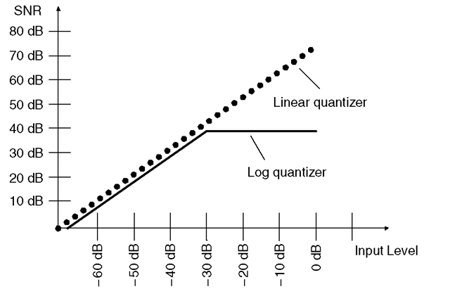
Figure 2.9 G.711 signal-to-noise ratio.
• SNR for linear quantizer: max = 74 dB (…);
• SNR for log type (A- or |x-law) quantizer: max = 38 dB ( —).
The G.711 encoding process can be built very easily from off-the-shelf integrated circuits (priority encoders, etc.). G.711 encoding and decoding requires a very low processing power (hundreds of channels can be decoded in real time on a simple PC). In the early days of digital telecommunications, this was mandatory.
We will see that new coders are designed to give the same degradation for a lower bit rate:
• The required processing power increases (mainly for the coding part).
• The coding process introduces more delay (this is because coders need to look at more than one sample of the original signal before being able to produce a reduced bitrate version of the signal).
