TCP Congestion Mechanism
The current TCP implementations in most operating systems are very much influenced by two legacy TCP implementations called Tahoe and Reno. Their essential algorithms and specifications originate with UNIX BSD versions 4.3 and 4.4, and no doubt some eventful hiking trip. The enhancements added by Tahoe and Reno focused on the TCP delivery mechanism. TCP uses a mechanism called slow-start to increase the congestion window after a connection is initialized. It starts with a window of one to two times the MSS. Although the initial rate is low, it increases rapidly. For every packet acknowledged, the congestion window increases until the sending or receiving window is full. If an ACK is not received within the expected time, the TCP stack reduces its speed by reverting to slow start state, and the whole process starts all over again. Congestion avoidance is based on how a node reacts to duplicate ACKs. The behavior of Tahoe and Reno differ in how they detect and react to packet loss:
Tahoe detects loss when a timeout expires before an ACK is received or if three duplicate ACKs are received (four, if the first ACK has been counted). Tahoe then reduces the congestion window to 1 MSS and resets to the slow-start state. The server instantly starts retransmitting older unacknowledged packets, presuming they have also been lost.
Reno begins with the same behavior. However, if three duplicate ACKs are received (four, if the first ACK has been counted), Reno halves the congestion window to the slow-start threshold (ssthresh) and performs a fast retransmission. The term "fast retransmission" is actually misleading; it’s more of a delayed retransmission, so, when the node has received a duplicate ACK, it does not immediately respond and retransmit; instead, it waits for more than three duplicate ACK before retransmitting the packet. The reason for this is to possibly save bandwidth and throughput in case the packet was reordered and not really dropped. Reno also enters a phase called Fast Recovery. If an ACK times out, slow-start is used, as with Tahoe.
In the Fast Recovery state, TCP retransmits the missing packet that was signaled by three duplicate ACKs and waits for an acknowledgment of the entire transmit window before returning to congestion avoidance. If there is no acknowledgment, TCP Reno experiences a timeout and enters the slow-start state. The idea behind Fast Recovery is if only one or a few packets are missed, the link was not truly congested, and rather than falling back to a complete slow- start, it should only reduce throughput slightly. Only when the server starts completely missing duplicate ACKs (sometimes called negative ACKs) should the stack fall back to slow-start. Once an ACK is received from the client, Reno presumes the link is good again and negotiates a return to full speed. By the way, most network operating systems today are based on the Reno implementation.
Both Tahoe and Reno Stacks reduce the congestion window to 1 MSS when a timeout occurs, that is, if no ACK whatsoever has been received.
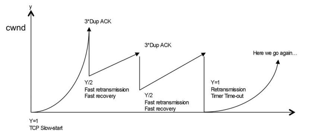
In summary, for operating systems based on the Reno TCP stack, the rate and throughput are maintained as long as possible to avoid fall back to TCP slow-start with one MSS size packet. The congestion avoidance and slow start are a continuous process during the TCP session (see Figure 4.7 ).
TCP Congestion Scenario
In real-world, high-performance networks, not everything works as described in topics that were written when networks were based on modems and serial lines, and when retransmissions occurred right after the first duplicate ACK was received. Drops because of congestion or link failures can occur, but the actual retransmission occurs some time after, because frankly, many packets are in flight. The issue gets more complex if a drop occurs and both the sender’s congestion window and receiver’s window are huge. Reordering TCP segments is a reality, and clients need to put the segments back into the right sequence without the session being dropped or else too many packets will need to be retransmitted.
Figure 4.7 TCP throughput vs congestion avoidance
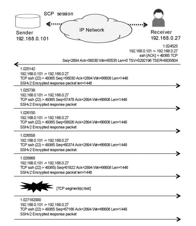
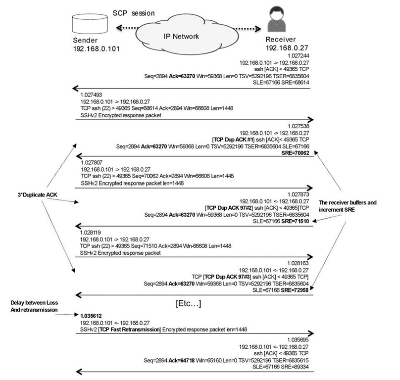
Let’s return to our earlier TCP session, to see how TCP stacks currently work in case of congestion and drops (see Figure 4.8). In Figure 4.8 . the receiver generates duplicate ACKs to notify the sender that segments are missing, resulting in a retransmission. The delay between the event that caused the loss, and the sender becoming aware of the loss and generating a retransmission, doesn’t depend on just the Round-Trip Time (RTT). It also depends on the fact that many packets are "in flight" because the congestion windows on the sender and receiver are large, so client retransmission sometimes occurs after a burst of packets from sender. The result in this example is a classic reorder scenario as illustrated in Figure 4.9 .
In Figure 4.9 . each duplicate ACK contains the SCE/SRE parameters, which are part of the Selective Acknowledgment (SACK) feature. At a high level, SACK allows the client to tell the server (at the protocol level) exactly which parts of a fragmented packet did not make it and asks for exactly those parts to be resent, rather than having the server send the whole packet, which possibly could be in many fragments if the window is large. Each duplicate ACK contains information about which segment (that is, which bytes) was missing, avoiding retransmission of every segment following the missing segment if they have been safely delivered. In summary, TCP can take a fair beating and still be able to either maintain a high speed or ramp up the speed quickly again despite possible retransmissions.
PMTU
Because the speed of long-lasting TCP sessions is so dependent on the ability to have a large MSS, it is crucial to be able to be as close as possible to the largest achievable IP MTU.
Figure 4.8 Segment loss
At the time of this writing, it is safe to state that an IP MTU of less than 1500 bytes, minus the protocol overhead, is one of the most common packet sizes because of Ethernet’s impact at the edge of the network. Therefore, it’s the most common packet size that carriers try to achieve. But tunneling solutions such as Wholesale L2TP and VPN-based MPLS, have introduced packets with larger MTUs due to their extra overhead, and either the IP packets need to get smaller or the media MTU of the links needs to get bigger, which in a Layer 2 switching environment sometimes is not an easy task. Thus, the MTU needs to be known for the path of the TCP session because of TCP’s greediness and the way it tries to increases a session’s performance.
One obvious issue with sessions that traverse several routers and links on their path to the egress receiver node, is to find out which MTU can be used. Information is needed to determine how to maximize the throughput, while at the same time avoiding packets being dropped because they exceed the MTU of any link on any node along the path. Determining the path MTU is a task for the source. If the Don’t Fragment (DF) bit has not been set, routers can fragment TCP packets, but this is an "expensive" task for the node and for the receiver, which must reassemble the complete packets from the fragments.
Figure 4.9 Retransmission delay
However, most operating systems solve this issue with Path MTU (PMTU) discovery, described in RFC 1191 – 2]. The PMTU algorithm attempts to discover the largest IP datagram that can be sent without fragmentation through an IP path and then maximizes data transfer throughput.
The IP sender starts by sending a packet to the destination with the MTU equal to its own link MTU, setting the DF flag on the outgoing packet. If this packet reaches a router whose next-hop link has an MTU on the outgoing interface that is too small, it discards that packet and sends an Internet Control Message Protocol (-CMP- "Fragmentation needed but DF set" error (type 3, subtype 4) to the source, which includes a suggested/ supported MTU. When the IP sender receives this ICMP message, it lowers the packet MTU to the suggested value so subsequent packets can pass through that hop. This process is repeated until a response is received from the ultimate destination.
Most modern operating systems today support PMTU by default. From the host side, PMTU is most useful for TCP, because it is a session-oriented protocol. However, it is also used in most routing software for various items, including establishing GRE tunnels, to secure the proper MTU for the tunnel path and to avoid fragmentation. However, an issue with PMTU is that it needs ICMP messages. It is possible that routers in the reverse path between the router reporting the limited MTU, and the IP sender, may discard the ICMP error message as a result of filters or policers for ICMP traffic. Here, PMTU fails because the sender never receives the ICMP messages and therefore assumes that it can send packets to the final destination using the initial MTU.
QOS Conclusions for TCP
Obviously, there are limited examples of steady, predictably behaved TCP flows in large networks. TCP always try to get more, with the result that it will be taken to school by the network and be shaped due to jitter in arrival, reorder of segments, drops, or session RTT timeouts. The TCP throughput and congestion avoidance tools are tightly bound to each other when it comes to the performance of TCP sessions. With current operating systems, a single drop or reordering of a segment does not cause too much harm to the sessions. The rate and size of both the receiver window and the sender cwnd are maintained very effectively and can be rapidly adjusted in response to duplicate ACKs.
Unless some advanced application layer retransmission function is used, which is rare, TCP is effectively the only protocol whose packets can be dropped in the Internet. There is a thin line between maintaining the pace of TCP sessions and avoiding too many retransmissions, which are a waste of network resources. No one wants to see the same packet twice on the wire unless absolutely necessary.
Several features and tools discussed later in this topic are designed to handle pacing of TCP sessions, for example, RED, token bucket policing, and leaky bucket shaping. Some of these tools are TCP-friendly, while others are link- and service-based. These tools can be used to configure whether a certain burst is allowed, thereby allowing the packet rate peak to exceed a certain bandwidth threshold to maintain predictable rates and stability, or whether the burst should be strictly controlled to stop possible issues associated with misconfigured or misbehaving sources as close to the source as possible. These tools can also be used to configure whether buffers are large, to allow as much of burst as possible to avoid retransmissions and keep up the rate, or small, to avoid delay, jitter and the build-up of massive windows, which result in massive amounts of retransmissions and reordering later on.
Real-Time Traffic
It can safely be stated that the main reason for a QOS is the need to understand how to handle real – time traffic in packet-based forwarding networks. In fact, if it were not for real – time traffic, most Internet carriers and operators, and even large enterprise networks could run a QOS-free network and most users would be happy with the level of service. What many people do not know is that by default, most Internet classroom routers that have been around for a while, prioritize their own control plane traffic from transit traffic without making any fuss about it. However, real-time traffic has changed everything, and without many end users being aware of it, most real-time traffic today is actually carried by packet-based networks regardless if it originates from a fixed phone service in the old PSTN world or from a mobile phone.
Anatomy of Real-Time Traffic
So what is real-time traffic? Consider the following points:
• Real-time traffic is not adaptive in any way. There can be encoders and playback buffering, but in its end-to-end delivery, it needs to have the same care and feeding.
• You cannot say real-time traffic is greedy. Rather, it requires certain traffic delivery parameters to achieve its quality levels and ensuring these quality levels demands plenty of network resources. If that traffic volume is always the same, delivery does not change. It is like a small kid who shares nothing whatsoever.
• Real-time traffic needs protection and baby-sitting. Rarely can lost frames be restored or recovered, and there is only one quality level: good quality.
Real-time traffic services come in many shapes and formats. The two most widely deployed are voice encapsulated into IP frames and streamed video encapsulated into IP frames with multicast addressing, in which short frames typically carry voice and larger frames carry streamed video. Services can be mixed as with mobile backhaul (more of that later in the topic), in which voice, video, and data all transit over the same infrastructure. In theory, the same device can receive non-real-time and real-time traffic. An example is a computer or 3G mobile device that is displaying streamed broadcast media. Real – time traffic packets themselves can vary tremendously in size, structure, and burstiness patterns. The packets can be of a more and less fixed size, relatively small voice packets, or bigger packets for broadcasting streamed media, in which many frames are encapsulated within one IP packet. Packets can have many headers depending on the transport media. For example, an IP packet can also have Ethernet 802.1q headers or MPLS stack labels. Most packets carry a UDP header and some form of helper transport protocol such as RTP. (We discuss the help provided by these transport protocols later in this topic.) However, all forms of real-time traffic have one thing in common: they all demand predictable and consistent delivery and quality, and there is little or no room for variation in networking service. Also, in most situations the bandwidth, delay, and jitter demands of real-time traffic can be calculated and therefore predicted.
RTP
It is impossible to write about real-time traffic without discussing the Real Time Protocol (RTP, . For many forms of realtime applications, RTP is the most suitable transport helper. RTP is defined in RFC 3550 [3], which replaces RFC 1889. RTP is often called the bearer part of a real-time session, because it carries the actual real-time data, such as the voice or streamed media. The size of packets in RTP is not particularly important. What is important is the fact that RTP successfully transforms the IP packet into a part of a stream. RTP does this with four key parameters in the header: the Sequence Number, the Timestamp, the Type, and the Synchronization Source Identifier. The Sequence Number is a 16-bit field that the sender increments for each RTP data packet in the same flow and that the receiver uses to keep track of the order of frames. With this information, the receiver can restore packet sequence if frames are out of order. Having the unique sequence number also provides a mechanism to detect any lost frames. The Timestamp is a 32-bit field that reflects the sampling instant of the first octet in the RTP data packet. Specifically, it is a clock that increments monotonically and linearly to allow synchronization and jitter calculations. The Timestamp allows the original timing of the payload to be assembled on the egress side, thus helping to maintain that payload quality. The Type field notifies the receiver of what type of data is in the payload. The Synchronization Source Identifier ( SSRC ) is a 32 – bit field that identifies the originator of the packet.
RTP works hand in hand with the RTP Control Protocol (RTCP). This control protocol provides the signaling for RTP, which is the data of the session. The primary function of RTCP is to provide feedback on the quality of the data distribution and to provide statistics about the session. RTP normally uses the even UDP port numbers and RTCP the odd port numbers, and RTCP packets are transmitted regularly within the stream of RTP packets. Figure 4.10 shows the rate of the RTCP packets sent within an RTP session. Note the packet number range between the RTP packets.
RTP receivers provide reception quality feedback by sending RTCP packets, which take one of two forms depending on whether the receiver is also a sender. An example is a SIP session, in which the node is obviously both receiver and sender (SIP will be discussed later in the topic). The two types of packets for sending feedback are similar except for their type code. How RTP and RTCP function with regards to QOS is no mystery. In most situations, there are one control and one forwarding part within the session. In most situations, the two are dynamically set up within the same port range. The data parts have even port numbers, and the control parts have odd port numbers.
Figure 4.10 The RTCP control packet rate ratio versus RTP packets
They are, for obvious reasons, different in size and volume. The size of data RTP packets is based on their content. For example, voice with a certain codec results in RTP packets of a certain size. RTCP packets are normally not very big because only a few are sent and they feedback only a relatively limited amount statistical information. Regardless of the difference in packet size, RTP and RTCP packets belong to the same real-time session and are so closely bound together that it probably makes the best sense to place them in the same traffic class and possibly in the same queue. However, it is probably not wise to have large size streaming broadcast media and small size voice in the same queue because of differences in queue sizes and because of the possibility of bursts. We compare these two topics in the next section.
VOIP
This topic is about QOS and so cannot detail all possible Voice over IP signaling protocols. There have been several of these protocols already, and there will no doubt probably be more, so we do not discuss H.xxx protocol suites or G.xxx encoders. We can agree, though, that some person’s ear is waiting for packets to traverse the network and arrive at their VOIP headset. Thus, in regards to QOS, voice flows are very different from any short-lived or long-lasting TCP sessions, such as those that carry HTTP request and reply transactions. But VoIP does not present itself in one consistent form. At one end are end-user VOIP solutions in which user-to-user or user-to-proxy calls are established directly. At the other extreme are big trunking solutions, in which the signaling and bearer channels of more traditional native voice equipment are trunked over an IP/MPLS network.
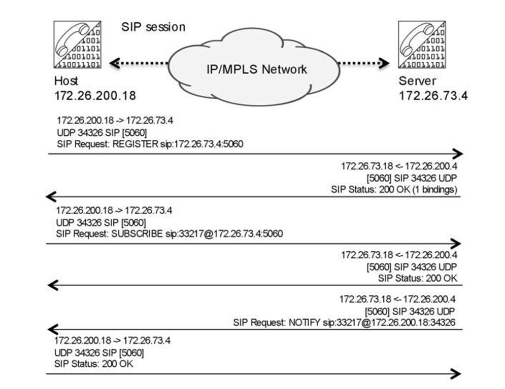
Let us focus on one of the more popular IP-based voice protocols, Session Initiation Protocol (SIP) , describing how it works so we can assess the demands it makes on a packet, based network. SIP, defined in RFC 3261 [4], which replaces RFC 2543, is a signaling protocol that is widely used for controlling multimedia communication sessions such as voice and video calls over IP. Once a call is set up, the actual data (bearer) is carried by another protocol, such as RTP. In its most basic form, SIP is a context-based application very similar to HTTP and uses a request/response transaction model. Each transaction consists of a client request that invokes at least one response. SIP reuses most of the header fields, encoding rules, and status codes of HTTP, providing a readable text-based format. It also reuses many IP resources such as DNS. Because very different types of traffic are associated with SIP, placing all SIP "related" packets in the same traffic class and treating them with the same QOS in the network is neither possible nor recommended. Let us start by focusing on the primary functions of SIP. First, the SIP device needs to register to a server. Figure 4.11 shows a simple registration phase, in which a soft-phone SIP device registers with its server. Note SIP uses ports 5060 and 5061.
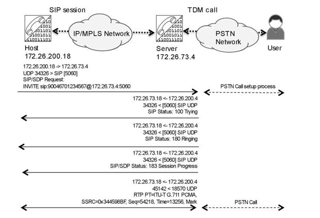
The actual call setup when a proxy server is used is trivial compared to many other VOIP systems, such as H323. Once the SIP call setup is done, the actual stream uses UDP-based RTP-encapsulated packets, as illustrated in Figure 4.12.
SIP uses Session Description Protocol (SDP) as a helper to glue it together. The SDP packet carries information and negotiates many items to establish a SIP call. One of the important items is which codec to use so that the egress side has all the correct synchronization information to be able to reassemble the payload correctly.
Figure 4.11 SIP register process, the classical 200 Ok messages
Figure 4.12 SIP Call setup via SIP proxy to PSTN
SIP session is mostly sampled using the G.711 codec. While perhaps not the most efficient codec, it is very reliable and provides good quality because it follows Nyqvist theory, sampling at twice the highest frequency being used. With regards to VOIP, it is important to note that SIP and SDP are only a few of the protocols involved in establishing calls. For example, DNS performs name resolution and NTP is used to set the time. Even if we ignore all non-SIP protocols and just focus on the call/data-driven packets, a QOS policy design question arises here: what part of the voice session should be defined as VOIP and be handled as such? Should it be only the actual dataflow that is the UDP RTP packets on already established calls? Or should the setup packets in the SIP control plane also be included? Should the service involved with DNS, NTP, syslog, and so forth, also be part of the service and traffic class? Or are there actually two services that should be separated, one for the control plane and one for forwarding (that is, for the bearer part of establish sessions)? The dilemma here is that if everything is classified as top priority, then nothing is "special" anymore.
Actual bandwidth estimates are all based on codecs in combination with encapsulation. But a SIP setup using, for example, G.711 over UDP and RTP, results in approximately 180-byte packets if the link media header is excluded. The SIP setup packets, however, have variable sizes. In summary, SIP packet lengths vary considerably between consecutive packets, while RTP packet are always the same length.
