The first part of this topic presented the policer and shaper tools as black boxes and gave a high-level view of their functionalities. This topic goes one step further and takes a closer look at the fundamental mechanics of these tools.
Policers are implemented using the concept of a token bucket, while shapers use leaky buckets. These are the two key concepts on which this topic focuses. We explain both, and compare the two in terms of applicability and differences regarding how to use them to deal with traffic burstiness and excess traffic.
Token Buckets
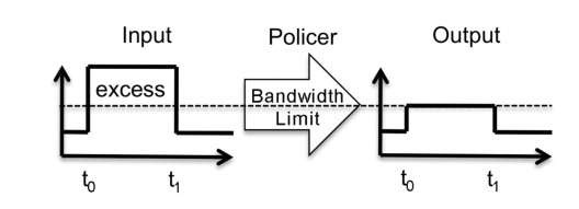
When viewed as a black box, the policer operation is pretty straightforward: at the ingress is a traffic flow with a certain bandwidth value, and at the egress is the "same" traffic flow that is now enforced to conform to the bandwidth value defined by the policer. One result is that "excess traffic" is discarded, a behavior also commonly called rate limiting. This policer operation is illustrated in Figure 6.1.
In Figure 6.1, the policer limits the input traffic to a certain bandwidth limit (represented as a dotted line). During the time interval between t0 and t1, the input traffic exceeds the bandwidth limit value, which results in the excess traffic being discarded by the policer. While it is not mandatory, the usual action taken regarding excess traffic is to discard it. There are several other possible actions, such as accepting the excess traffic and marking it differently so that when both excess and non-excess traffic types are past the policer tool, the router can still differentiate between them and apply different behaviors if desired. However, for ease of understanding, throughout this topic we assume that the policer discards excess traffic, a behavior commonly called "hard policing."
Figure 6.1 High-level view of the policing operation
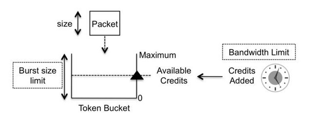
Figure 6.2 Token bucket structure
The previous paragraph is a very quick recap of the high-level view of the policer tool as presented in Part One of this topic. Now, let us look closer at the fundamental mechanics of the policer.
A policer is implemented using a token bucket algorithm for which there are two key parameters, the bandwidth limit and the burst size limit. The bandwidth limit is the rate at which traffic flows when leaving the policer, and the burst size limit parameter represents the policer’s tolerance to traffic burstiness. These two parameters are usually measured in bits per second and bytes, respectively.
A token bucket operates using the concept of credits. When a packet of a certain size (also commonly called a length) arrives at the token bucket, the key question is whether there are enough credits to serve the packet. Put another way, the question is whether the packet should go through the policer (be transmitted) or should be discarded (be policed). The depth, or height, of the bucket is specified by the burst size limit parameter, while the bandwidth limit represents the credit refill rate, as illustrated in Figure 6.2.
So how does this credit scheme work? The triangle symbol in Figure 6.2 represents a meter that indicates how many credits are available inside the token bucket. As packets cross through the token bucket, the ones that are transmitted consume credits and the ones that are discarded do not. The burst size limit parameter specifies the bucket depth, that is, the maximum number of credits that are available at any given moment in the token bucket.
The credit consumption of transmitting a packet is a function of its size, so every time a packet is transmitted, the triangle meter decreases as a function of the packet size. In parallel, the bucket is periodically refilled with a certain number of credits that is a function of the bandwidth limit parameter. But for now, let us pretend that the credits are not refilled.
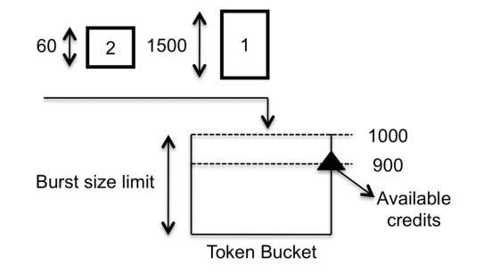
Figure 6.3 Two packets arriving at the token bucket
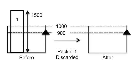
Figure 6.4 Packet discarded by the token bucket
As an example to illustrate how credits are consumed, let us start with a token bucket that has a burst size limit of 1000 bytes and that has 900 available credits. Two packets, numbered one and two with sizes of 1500 and 60 bytes, respectively, arrive sequentially at the token bucket, as illustrated in Figure 6.3.
The first packet, at 1500 bytes, is larger than the number of available credits, so it is discarded. The number of available credits in the token bucket remains at 900, because the packet was not transmitted and hence no credits were consumed, as illustrated in Figure 6.4.
Before considering the second packet, it is worth pointing out that because the token bucket depth is 1000, any packets larger than this value are always discarded. Or put more generally, in a token bucket, packets whose size is larger than the burst size limit are always discarded.
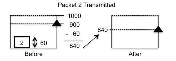
The second packet is 60 bytes long, which is smaller than the number of available credits, so the packet is transmitted. The number of available credits becomes 840, which is the difference between the number available before the packet entered the bucket and the size of the transmitted packet, as illustrated in Figure 6.5.
The reader can easily foresee from the logic of this example that the credits in the token bucket will always deplete completely. To refill the bucket, a mechanism of refilling the credits is working in parallel.
Figure 6.5 Packet transmitted by the token bucket
Figure 6.6 Starting point for a token bucket with credit refill
The credit refill rate works in a timed fashion. Imagine that a clock is ticking, and with every single tick, a certain number of credits are added to the token bucket, where the number of credits added is a function of the bandwidth limit parameter and the time interval between each tick is usually a hardware-dependent parameter. However, credits are not added infinitely. As a rule, the maximum number of available credits that a token bucket can have at any time is always the value of the burst size limit value (the bucket depth). If no credits are being consumed because no packets are being transmitted, the clock continues to tick and credits continue to be added to the token bucket until the maximum value of available credits is reached and the bucket is full. This value is always capped at the burst size limit value.
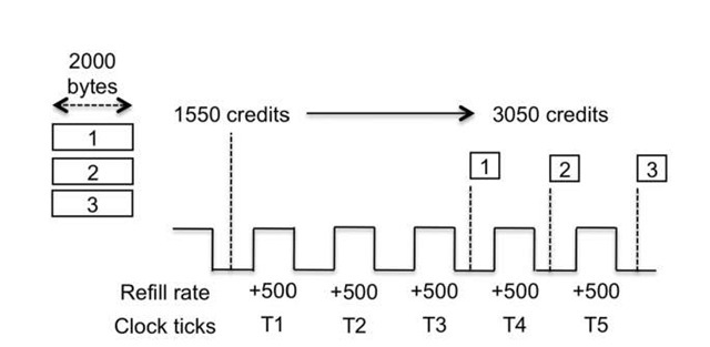
We are now ready to present an illustration of the full operation of a token bucket that is simultaneously being depleted of credits and actively refilled with credits. The starting point is a token bucket configured with a burst size limit of 6000 bytes, and after the last packet was transmitted, the number of available credits is 1550 bytes. The bandwidth limit value is configured such that with every clock tick, 500 bytes worth of credits are added. For three consecutive clock ticks, no packets have arrived at the token bucket, thus raising the available credit value to 3050 (1550 plus three times 500). Now assume that after the end of the third, fourth, and fifth clock ticks, three packets numbered one through three, all with a size of 2000 bytes, arrive at the token bucket, as illustrated in Figure 6.6.
Figure 6.7 Packet one is transmitted
Figure 6.8 Packet two is discarded
In this example, we synchronize the arrival of the packets with the end of clock ticks. This is done solely for ease of understanding.
When packet number one is placed in the token bucket, the number of credits available is 3050, which is greater than the packet size. Therefore, this packet is transmitted, and the available credit value is updated to the value it had before packet one arrived (3050) minus packet one’s size (2000). This results in 1050 credits being available, as illustrated in Figure 6.7.
After packet one is transmitted, clock tick T4 occurs, which adds 500 bytes of credits to the current value of 1050, thus resulting in a total of 1550 available credits. Now, following Figure 6.6 , packet number two arrives at the token bucket. The packet size of 2000 is larger than the number of available credits, so the packet is discarded and the number of credits remains at 1550, as illustrated in Figure 6.8.
At clock tick T5, 500 more bytes of credits are added to the token bucket, raising the number of available credits to 2050. The size of packet number three is 2000 bytes, less than the number of credits available in the bucket, so this packet is transmitted, leaving the number of available credits at 50.
The aim of this example is to illustrate how a token bucket works with regard to the two values configured in a policer, the bandwidth limit and burst size limit. In a nutshell, the meter of available token bucket credits varies between zero and the burst size limit value, and the credit refill rate is a function of the configured bandwidth limit value.
As a teaser to open the topic of absorbing traffic bursts, the end result of the above example is that packets one and three are transmitted and packet two is discarded. Now assume the same scenario, but consider packets arriving at the token bucket at a faster pace. For example, if all three packets arrive between T3 and T4, only packet one is transmitted and the other two are dropped, because no credit refills occur until T4. As illustrated in Figure 6.7 , after packet one is transmitted, the number of available credits is 1050, insufficient for transmitting either of the other two packets.
Traffic Bursts
A traffic burst can be seen as an abrupt variation in a traffic pattern. Bursts are an unavoidable fact in the networking world, because even if the traffic pattern rate is perfectly flat, just the initial jump or ramp from having no traffic whatsoever to that constant rate is itself a burst.
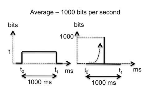
Let us start with an extreme example. Suppose a source of traffic is connected to a policer and the bandwidth limit implemented is 1000 bits per second (bps), which translates to one bit per millisecond. As illustrated in Figure 6.9 , whether the source sends traffic at a rate of one bit per millisecond or sends 1000 bits in one millisecond, and nothing more is sent during that second, both scenarios conform to an average bandwidth of 1000 bps.
However, in the second scenario, there is a traffic burst, an abrupt variation in the traffic pattern, as illustrated in Figure 6.9, because all the traffic that could be said to be expected to be spread more or less across one second is sent in a single millisecond. What this means is a faster credit consumption in the token bucket in a shorter interval of time, which can lead to packets being discarded because as the time gap between the arrival of packets shrinks, fewer credit refill cycles occur, so a credit depletion scenario becomes more likely. As with many things in the QOS realm, discarding traffic bursts can be good or bad, depending on the desired goal.
Increasing the capability of the policer for burst absorption is directly connected to increasing the available credits present in the token bucket, which is a function of the burst size limit and the credits refill rate (which itself is a function of the bandwidth limit value). However, the bandwidth limit is a constant value, because it represents the bandwidth the policer must implement to handle the input traffic. If the desired goal of the policer is to implement an X bps rate, the bandwidth limit must be set to that value of X, which leaves only the burst size limit value as the only variable.
Figure 6.9 Traffic burst
Figure 6.10 Ingress policer and output queue
Another relevant factor is the size of the packets. In terms of credit consumption, ten 100-bytes packets are equivalent to one 1000-byte packet, so the expected packet size should be taken into account when dimensioning the burst size limit of the policer. If the expected packet size is unknown, the only option is to consider the maximum packet size admissible into the logical or physical interface to which the policer is applied, a value called the MTU (Maximum Transmission Unit).
Accepting traffic bursts needs to be considered not just from a policer perspective, but also from a broader perspective as well, because the bursts place pressure on other QOS tools and on router resources. To illustrate this, we use the example illustrated in Figure 6.10. When traffic arrives at a router, it is classified and policed on the ingress interface, and as a result of the classification it is mapped to queue A on the egress interface.
Assuming the rate purchased by the customer is X bps, this rate logically becomes the value to which the policer bandwidth limit parameter is set. In this scenario, the two remaining variables are the policer burst size limit and the length of queue A. Logically speaking, these two variables are interconnected. Accepting high traffic bursts at the policer makes no sense if the length of the output queue is small, because it will fill up quickly. The result is that packets that are part of that traffic burst are accepted by the policer, only to be dropped at the egress interface because the output queue has filled up. Thus these packets are consuming router resources in the transit path from the ingress interface until reaching the egress queue.
As previously discussed, the queue length can be seen as a measure of the maximum possible delay introduced to a packet that is mapped to that queue. A longer queue allows more packets to be stored, at a possible cost of introducing more delay, while smaller queues minimize the risk of delay and jitter, at a cost of being able to store fewer packets.
The policer operation either transmits or discards a packet, but it never introduces any delay into the traffic transmission, so in the scenario illustrated in Figure 6.10, the delay inserted into the traffic crossing the router is controlled by the length of queue A. Once again, a division can be made between real-time and non-real-time traffic. The burst size limit value should be smaller for real-time traffic than for non-real time traffic because queues used by real-time traffic ideally are small to minimize possible delay and jitter insertions. Keep in mind, however, that setting a very small burst size limit may lead to a scenario in which the credits in the token bucket are repeatedly being depleted.
For non – real – time traffic, the burst size limit can be higher because the output queues usually also have a greater length, thus making it more likely for a high traffic burst admitted by the policer to fit in the output queue. However, this feature should not be seen as a criterion for using the highest possible value for the burst size limit parameter. Quite the opposite, really. Returning to the extreme example illustrated in Figure 6.9, we have a 1000-bit burst in a single millisecond in a policer with a bandwidth limit value of 1000 bps. To absorb such a burst, all other traffic sent during the remaining 999 milliseconds of that second is discarded, because this is the only possible way for the policer to conform to the configured bandwidth limit value of 1000 bps. It is acceptable to absorb bursts, but not acceptable for a single traffic burst to consume the entire bandwidth limit. While it is true that this is an extreme example, the reader should always keep in mind that although some traffic burstiness can be accepted, the amount of burst tolerance should be kept within reasonable boundaries.
Unfortunately, there are no simple or bulletproof formulas to calculate the burst size limit. The usual approach taken in the field is to start with a small value and increase it using a trial-and-error approach that is generally based on the outcome of lab testing, real network experience, or recommendations in the router vendor’s documentation. A starting point that both authors have found to be useful is to dimension the burst size parameter as a specific amount of the interface bandwidth on which the policer is applied. For example, on a gigabit interface, using a burst size limit value equal to 5 milliseconds of the interface bandwidth results in a value of 625000 bytes (1G multiplied by 5 ms and divided by 8 to convert from bits to bytes). When the interface bandwidth is considerably less than a gigabit, this rule may lead to a very small burst-size value. In this case, another rule of thumb is to dimension the burst size limit in terms of how many packets are allowed in a burst, for example, ten times the expected packet size or the link MTU. So for example, if the MTU value configured is 1500 bytes, the burst size limit value is 15,000 bytes.
So far we have considered traffic that contains bursts, abrupt variations in its pattern. To finalize the above discussion, let us now consider that the traffic crosses the policer at a perfect flat rate, without any bursts, and also that the traffic rate is always below the policer bandwidth limit parameter. The key point to retain is that packets crossing the policer still consume credits and as such, the burst size limit still needs to be adjusted to the expected pace at which packets arrive at the token bucket.
