Mixing Different QOS Realms
So far, we have discussed scenarios consisting of a single realm in which the same technology is used from the source to the destination. Single-realm networks make things easier from the perspective of classifying traffic. However, in the real world, it is common to have a mix of technologies between the traffic flow end points. For example, the end points can be located in IP realms that are connected by MPLS networks.
Conceptually speaking, from a traffic flow perspective, we can have a source network, one or more transit networks, and a destination network. The challenge with such scenarios is that when a change of realm results in a change in the granularity of the classifiers, lack of the number of classes of service and the associated PHBs that are available at each network may occur.
There are two distinct real4ife scenarios. In the first, the middle network belongs to a service provider that offers a set of standard services from which customers choose to use to interconnect its sites or networks. In this scenario, there is not much room for discussion because the customer picks services from a fixed set of available options.
The second scenario is one in which the middle network belongs to the same administrative domain as the source and destination networks. Because all three network segments are in the same domain, the classes of service and associated PHBs that are available on the middle network can be tuned to achieve the desired end^end consistency.
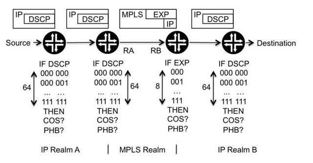
Let us start with an example of two IP realms (called A and B) and an MPLS realm in the middle. Routers belonging to each domain use the packets QOS markings as the classification parameter. This is illustrated in Figure 5.9.
Routers RA and RB are present at the border between the IP and MPLS realms. Traffic sourced in IP realm A travels to RA, where it is classified as an IP packet and then encapsulated into an MPLS tunnel. The traffic travels inside this tunnel to router RB, which classifies it as an MPLS packet, then decapsulates it and sends it into the IP realm B as an IP packet.
The two IP realms use the packets’ DSCP markings as the classification parameter, which provides a granularity of up to 64 distinct QOS markings per packet. On the MPLS network (through which the IP traffic travels encapsulated), the classification parameter used is the EXP field, which provides up to eight different QOS markings. So this seems to be a problem, because two realms in which the classifier granularity is 64, are being connected by a realm in which the classifier granularity is eight.
Figure 5.9 Connecting two IP networks via MPLS
Table 5.1 Classification rules in the IP realms A and B with four classes of service
|
IF DSCP field |
THEN class of service |
Respective PHB to be applied |
|
000 000 |
COS1 |
PHB1 |
|
000 001 |
COS2 |
PHB2 |
|
000 010 |
COS3 |
PHB 3 |
|
000 011 |
COS4 |
PHB4 |
In this situation, the first thing to bear in mind is that what matters is not the maximum granularity of the classifiers, which directly limits how many different classes of service can exist. The key point is not the maximum value but how many different classes of service must be implemented. That is, just because the DSCP field allows differentiating between 64 different types of packets, there is no obligation to implement 64 different classes of service in the network. The question should be how many classes of service are necessary rather than how to implement the maximum number.
Returning to the example in Figure 5.9, assume that IP realms A and B implement four different classes of service, and packets belonging to each class of service are identified by their DSCP marking, as illustrated in Table 5.1.
The MPLS realm uses classification based on the EXP markings, which also allows a way to differentiate between four different types of packets. So consistency between the two realms is achieved by implementing four classes of service in the MPLS realm that are associated with the same PHBs as the four classes of service used in the IP realms, as illustrated in Table 5.2 .
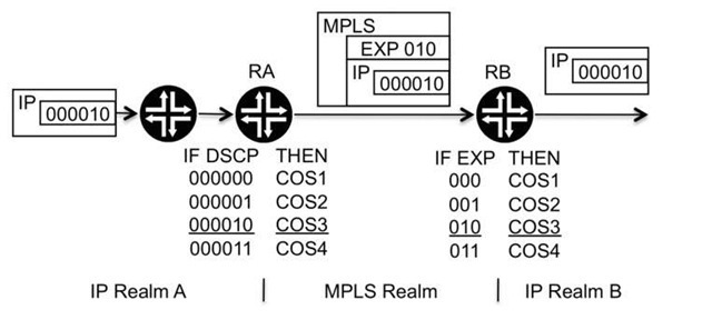
To make this example clearer, let us focus on a packet generated by the source that has the DSCP marking of 000 010. The packet arrives at router RA with this DSCP marking.
Table 5.2 Classification rules in the MPLS realm
|
IF EXP field |
THEN class of service |
Respective PHB to be applied |
|
000 |
COS1 |
PHB1 |
|
001 |
COS2 |
PHB2 |
|
010 |
COS3 |
PHB 3 |
|
011 |
COS4 |
PHB4 |
Figure 5.10 Packet traversing different realms
The classifier inspects the packet’s QOS field, finds the DSCP value, and based on the rules shown in Table 5.1, classifies it into the COS3 class of service. RA is the router sitting at the border between the IP A and MPLS realms, so it receives the packet as an IP packet but sends it towards RB with an MPLS label on top of it. So when the packet leaves RA towards RB, it is tagged by RA with an MPLS label that contains an EXP value of 010, as illustrated in Figure 5.10.
Router RB receives the packet with an EXP marking of 010 and, following the rules in Table 5.2 , it classifies it into the class of service COS3 and applies PHB3. Because RB is the router connecting the MPLS realm and the IP realm B, it removes the MPLS label before injecting the packet into IP realm B.
As long as on routers RA and RB, the PHB applied to packets belonging to COS3 is the same (it should be PHB3, according to Tables 5.1 and 5.2), consistency is achieved from the source to the destination.
The integration illustrated in Figure 5.10 is straightforward, because the classifiers present in the MPLS realm have enough granularity to differentiate traffic into the four different classes of service that are implemented in the IP realms.
The same scenario becomes more interesting if the IP realms implement more than eight classes of services. Table 5.3 illustrates a case with ten classes of service.
Table 5.3 Classification rules in the IP realms A and B with ten classes of service
|
IF DSCP field |
THEN class of service |
Respective PHB to be applied |
|
000 000 |
COS1 |
PHB1 |
|
000 001 |
COS2 |
PHB2 |
|
000 010 |
COS3 |
PHB 3 |
|
000 011 |
COS4 |
PHB4 |
|
000 100 |
COS5 |
PHB5 |
|
000 101 |
COS6 |
PHB 6 |
|
000 110 |
COS7 |
PHB7 |
|
000 111 |
COS8 |
PHB 8 |
|
001 000 |
COS9 |
PHB 9 |
|
001 001 |
COS10 |
PHB 10 |
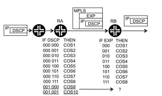
Figure 5.11 Exhaustion of the MPLS classifiers’ granularity
Having ten classes of service exhausts the granularity of the classifiers present in the MPLS realm, as illustrated in Figure 5.11.
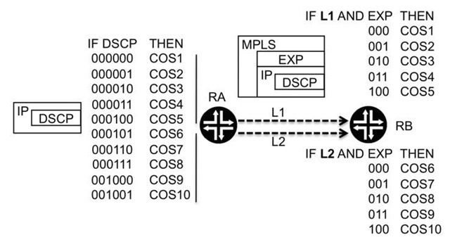
If an IP packet arrives at router RA with an DSCP marking of 001 000, it is classified into the class of service COS9. However, all the EXP markings inside the MPLS realm are already being used to identify traffic belonging to the classes of service from COS1 to COS8, so no more EXP values are available to identify traffic belonging to the class of service COS9, or, for that matter, to COS10.
As with many things in the QOS realm, there are several possible ways to solve this problem. We present one solution based on increasing the classifier granularity by using the information regarding the inbound interface on which traffic is received.
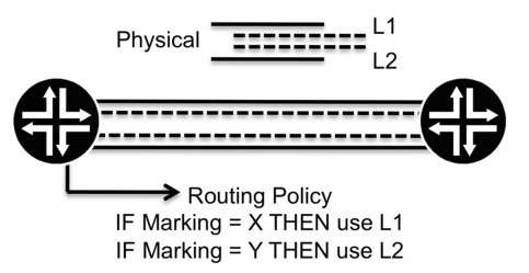
Figure 5.12 Mapping traffic to different tunnels according to the QOS marking
Table 5.4 Classification rules using the EXP field and interface
|
IF EXP |
Tunnel/Logical interface |
THEN class of service |
|
000 |
L1/1st |
COS1 |
|
L2/2nd |
COS2 |
|
|
001 |
L1/1st |
COS3 |
|
L2/2nd |
COS4 |
|
|
010 |
L1/1st |
COS5 |
|
L2/2nd |
COS6 |
|
|
011 |
L1/1st |
COS7 |
|
L2/2nd |
COS8 |
|
|
100 |
L1/1st |
COS9 |
|
L2/2nd |
COS10 |
|
|
101 |
Unused |
|
|
110 |
||
|
111 |
The physical interface that connects routers RA and RB is split into two logical interfaces. Two MPLS tunnels (named L1 and L2) are created between RA and RB, and L1 is established across the first logical interface and L2 over the second. At RA, rules are implemented so that the selection of the tunnel to reach RB (either L1 or L2) is done according to the packet’s QOS marking. This is accomplished with the help of routing policies, as illustrated in Figure 5.12.
The result of this split is that router RB receives traffic from two separate MPLS tunnels on two separate logical interfaces. When this tunnel arrangement is combined with classifiers that look at the packets’ QOS marking and that are specific for each logical interface, the desired ten classes of service inside the MPLS realm can be implemented, as illustrated in Table 5.4 .
Table 5.4 shows an overlap in that the same EXP marking is used to identify packets belonging to different classes of service. However, there is no ambiguity, because the value of the EXP field is used together with the information regarding the MPLS tunnel from which was the packet received. Returning to the network topology we used previously, Figure 5.13 illustrates the implementation of such a scheme.
Figure 5.13 MPLS classifiers based on the EXP and tunnel from which traffic is received
This scheme does work and accomplishes the desired goal, but it is achieved at the expense of increasing the complexity of the network. The solution requires the creation of multiple tunnels between the source and the destination, the usage of logical interfaces, the introduction of routing policies, and definition of classifiers on a peri nterface basis. For a scenario with only two routers in the middle network, the task is easily doable. However, it is not quite the same with routers of the order of tens or hundreds.
Conclusion
Currently, classification based on packet QOS markings is without a doubt the most popular and widely deployed method, because of its simplicity in terms of using fields standardized for each technology and its ease of implementation. The other two types of classifiers presented in this topic, interface-based and deep packet inspection, are commonly used as auxiliaries when it is necessary to increase granularity.
The maximum number of classes of service that can exist inside a QOS realm is limited by the classifier granularity. In addition, the required classifier granularity needs to be considered if there is a requirement to signal information between routers.
Mixing QOS realms may raise some challenges if there are differences between the granularity of the classifiers used in the different realms, as discussed in this topic. The solution is typically to increase the granularity by combining the packets’ QOS markings with other classification processes.
