Solution
Although BASIC is only capable of directly implementing 8-bit arithmetic, operations of any length are possible by breaking down the process into byte-sized chunks. In the case of addition, this involves a sequence of byte operations from the least to the most significant digits with any carry from the nth digit byte being added into the n + 1th summation. The least significant addition has a presumed carry-in of 0 and the carry-out from the most significant addition becomes the highest bit of the outcome. For example FF FFh + FF FFh = 1 FF FFh (65, 535d + 65,635d = 131,070d).
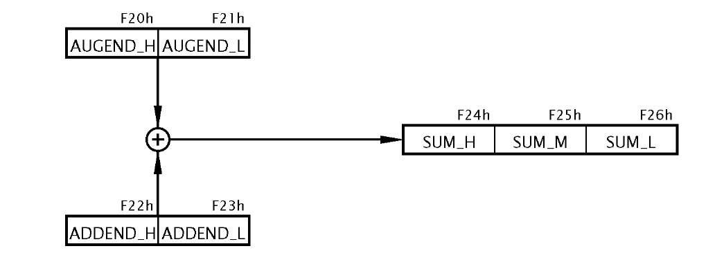
Fig. 3.8 The process.
The overall process is diagrammatically shown in Fig. 3.8. However, given that we need to implement the process as a sequence of steps executable by the byte-sized instructions of Table 3.1 then the next step is to produce a task listing.
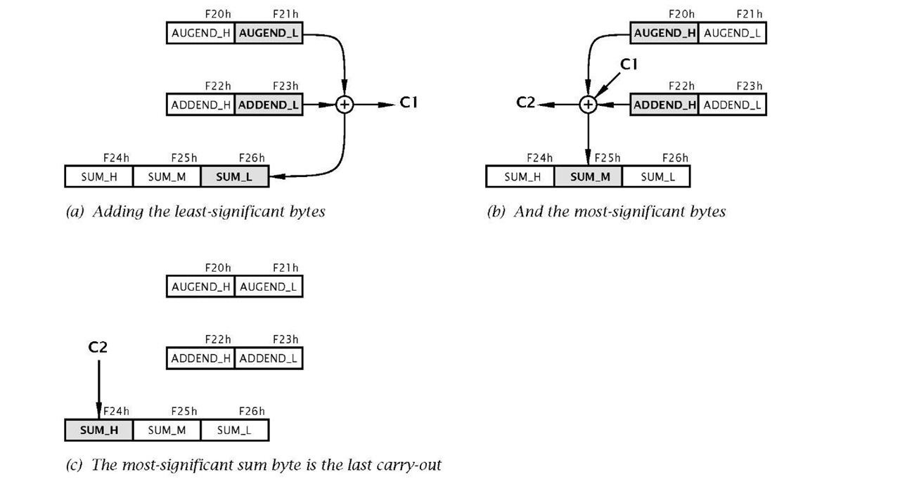
1. Add the low bytes of the augend and addend, generating the low byte of the sum and carry C1.
Fig. 3.9 Visualization of the task process.
2. Add the high bytes of the augend and addend plus the last carry-out C1 to give the middle byte of the sum and a new carry-out C2.
3. The high byte of the sum is the last carry-out C2, either 0 or 1.
Given that this is our first program of any substance, a detailed visualization of this task list will be useful. For most instances detail at this level is not helpful and subsequently we will use a more abstract visualization known as a flow chart (see Example 3.3).
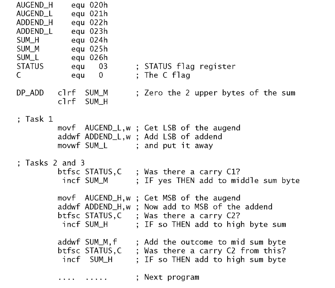
Once a task list has been established then the next step is to implement this as a sequence of instructions, that is the program. One possible is shown in Program 3.5.
In the listing the three tasks are identified by an appropriate comment.
Task 1
This comprises a Load-Add-Store sequence to add the lower byte of the addend to that of the similarly significant augend. The outcome byte is stored in memory at File 26h (SUM_L) and the Carry flag bit (bit 0 in File 3) is set as appropriate to C1 .
Program 3.5 The double-precision add program.
Task 2
If there was a carry-out from Task1 then the precleared middle byte of the sum is incremented as the carry-in C1 . Then the upper bytes of the addend and augend are added. The final outcome of SUM_M (in File 25h) is determined by adding its current state (00h or 01 h) to the outcome of this addition.
Task 3
Either of the two additions in Task 2 can result in a carry-out. The C flag in the STATUS register can be tested after each addition and if set, the upper byte of the sum SUM_H (File 26h) is incremented to add C2, as shown in Fig. 3.8(c). There will not be a carry-out generated by both the Task2 additions.
Example 3.3
Write a program to divide the byte in the Working register by ten. The quotient is to be in File 20h and the remainder in W.
Solution
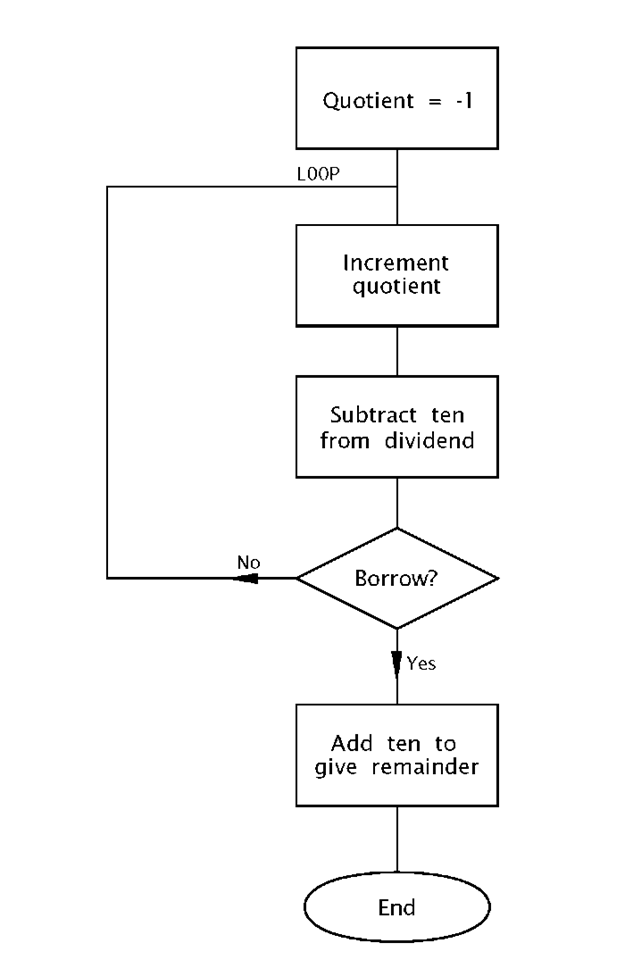
Division is the process in finding how many times the divisor (ten in our case) can be subtracted from the dividend without underflowing, that is producing a borrow.
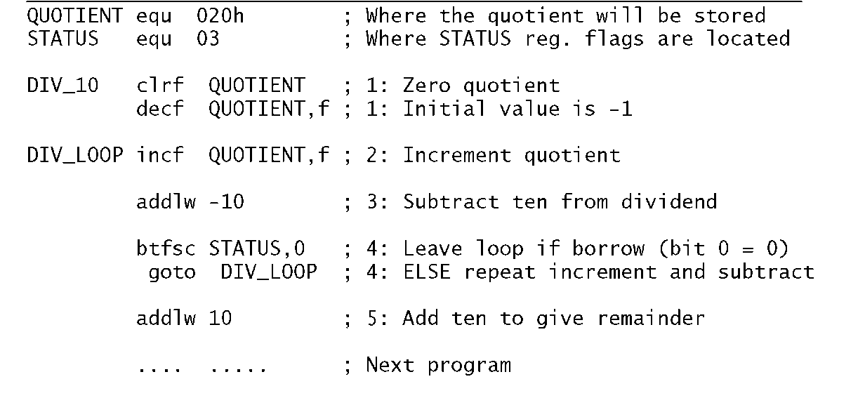
The flow chart shown in Fig. 3.10 outlines the task list to implement our algorithm. Initializing the quotient to -1 means that the subtract and increment loop can begin by incrementing, and this process will continue until a borrow is produced after the subtraction by ten process. A borrow-out indicates that the last subtraction was not successful in that the divisor (i.e. ten) was larger than the residue it was subtracted from. That is the outcome is negative. The loop count on exit represents the number of successful subtractions and thus the quotient.
The coding in Program 3.6 closely follows the flow chart, with comment numbers referring to the statement boxes. The actual subtract constant ten is implemented by adding minus ten! This is because the more obvious sublw 10 instruction actually subtracts W from ten and not ten from W. Notice the mechanism for exiting the loop by testing and skipping if bit0 in STATUS is clear after this subtraction.
Remembering that bit 0 in File 3 is the Carry flag doubling as the Borrow flag, then a borrow out is indicated if this bit is zero after the subtraction. On exit ten is added back on to compensate for the last unsuccessful subtraction and the outcome then gives the remainder.
Fig. 3.10 Division by repetitive subtracting.
Example 3.4
As part of a program to convert degrees Celsius to Fahrenheit it is necessary to multiply the byte in W by nine. Devise a suitable coding.
Solution
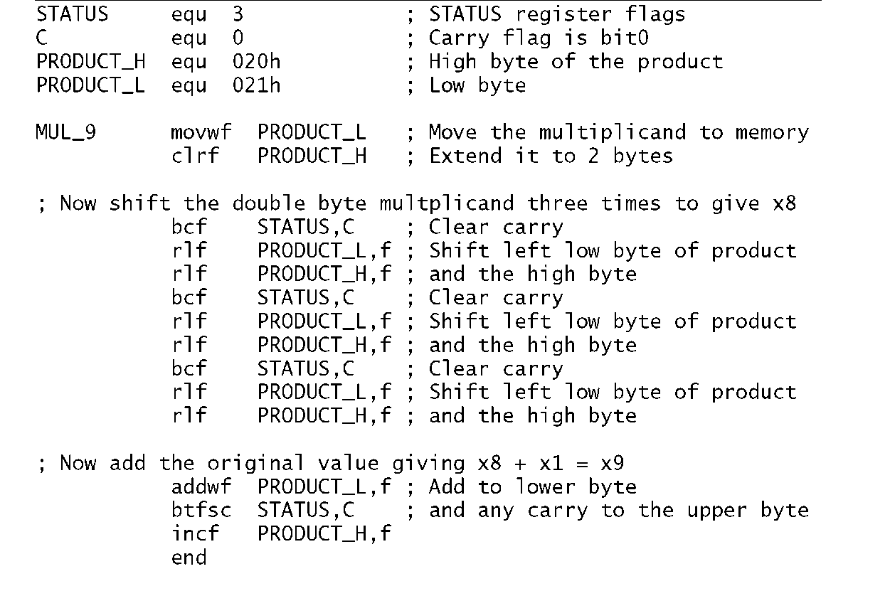
There are two ways of multiplying. The fundamental definition of multiplication is repetitive addition, thus we could add the datum nine times to implement our specified function. An alternative approach is the shift and add technique outlined.Thus the x9 function is implemented as x8 + x 1. The former is carried out by shifting left three times (i.e. 23). Thus we have:
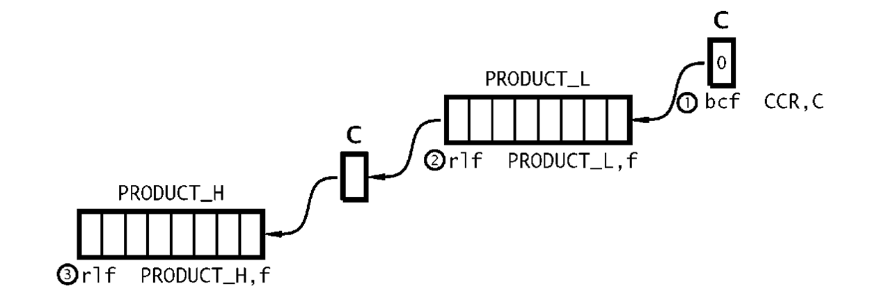
No matter what technique is used, the outcome by definition will be larger than either the multiplier or multiplicand. In this case we need two bytes. In the coding of Program 3.7 the two memory locations File 20h and File 21 h are used to hold the high byte and the low byte respectively of the final 2-byte product. By copying the multiplicand from W to the low byte and clearing the upper byte we make an extended 2-byte version of the multiplicand in Data memory. Shifting left is implemented by using the rlf (Rotate Left File) instruction twice, beginning with the lower byte. As well as shifting the byte PRODUCT_L left once, the most significant bit is moved into the Carry flag. Subsequently rotating the contents of the high byte PRODUCT_H moves this Carry in as the new least significant bit and shifts the high byte left as shown in Fig. 3.11. Of course the Carry flag needs to be cleared prior to this process. This 3-instruction double-precision routine is repeated three times to give the required x8 function. Adding the original multiplicand, which is still in W gives the final x9 function.
Program 3.7 Multiplying by nine.
Fig. 3.11 Double-precision shifting.
Example 3.5
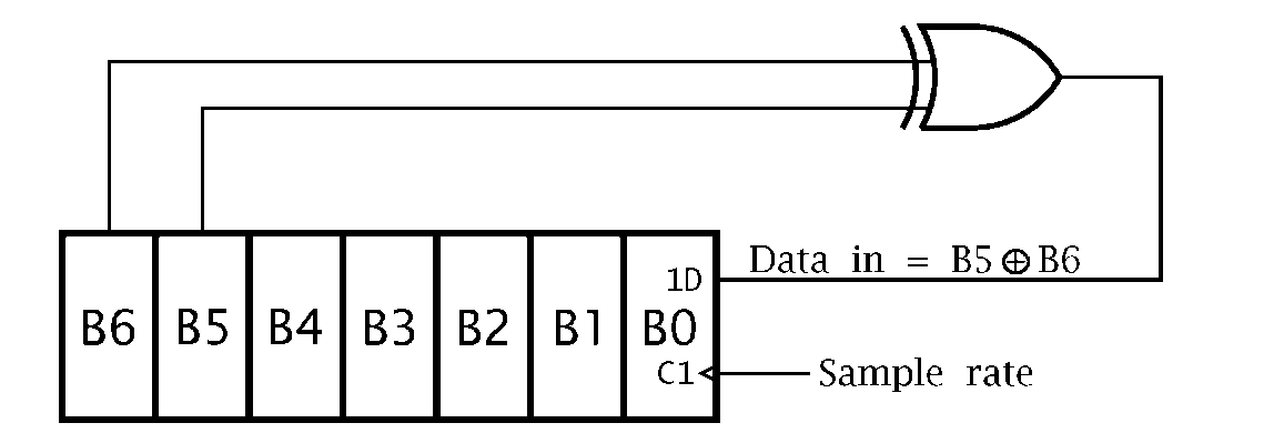
The circuit diagram of Fig. 3.12 shows a 7-bit pseudo-random number generator (PRNG) based on a shift register with an Exclusive-OR gate feedback. Devise a routine to continually send these 127 binary random numbers to a port located at File 06. The routine must initialize the PRN to any non-zero value.
Fig. 3.12 A 7-bit pseudo-random number generator.
Solution
A suitable task list is:
1. Initialize the number to 01.
2. DO forever.
(a) Rotate shift a copy of the number once left so that bits 5 & 6 are aligned.
(b) Bitwise XOR the number and its shifted copy.
(c) Rotate the outcome twice left to pop out bit 6 into the C flag, which will be B6®B5.
(d) Rotate the original number once left with C becoming the new bit 0.
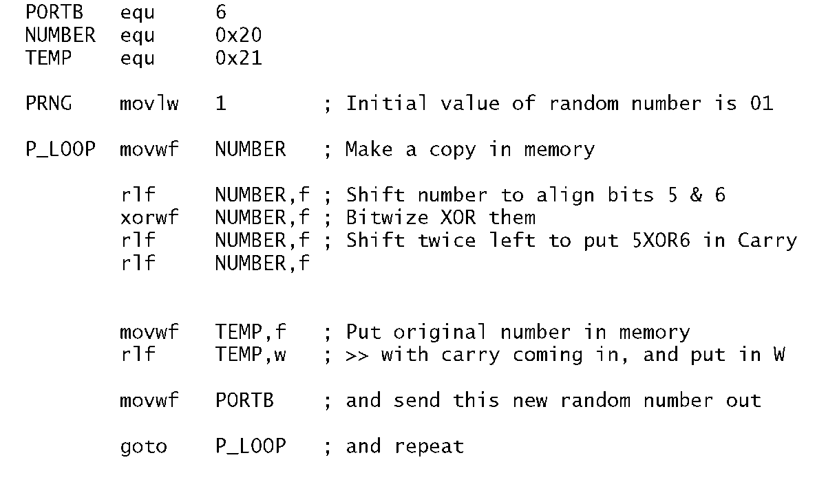
Program 3.8 A 7-bit pseudo-random number generator.
The listing in Program 3.8 follows the task list fairly closely. The value of the number is temporarily saved in memory so that it can be processed without altering the original number down in W. This is done by specifying the destination to be the file, eg. rlf NUMBER,f. After rotating left once left, bit 5 in the shifted copy in NUMBER is aligned with the original bit 6 in W. After exclusive ORing the two, with the destination again being in File memory (xorwf NUMBER,f), bit 6 in NUMBER is now B5®B6. Shifting twice left puts this bit in the Carry flag. Finally rotating the original pseudo-random number in W moves that pattern once left with the new least-significant bit being the Carry flag, that is B5®B6 as specified in the diagram. The first 32 hexadecimal values output are:
The sequence will repeat after 127 output values.
What would happen if the initial value of the random number was zero?
Self-assessment questions
3.1 How could you simply with one instruction toggle bit 0 of any file register?
3.2 As part of a Data memory testing procedure each file in the range File 0Ch through File 2Fh is to be set to the pattern 01010101 b (5 5h). Using Program 3.2 as a model, write a suitable coding to implement this task.
3.3 Write a program to subtract the double-byte datum which is located in File 22:23h, called NUM_2, from NUM_1 in File 20:21 h. The double-byte difference is to be in File 24:25h. Remember, if there is a borrow from the lower byte subtraction then an additional one must be subtracted from NUM_1 in the upper byte subtraction. Assume that NUM_2 is smaller or equal to NUM_1. If this were not so how could you determine this situation after the routine has been completed?
3.4 Write a routine that will determine how many hundreds there are in a byte in Data memory at File 20h. The outcome, which is to be in W, will either be 02h, 01 h or 00h. For example if the contents of File 20 are FFh (decimal 255) then the outcome will be two. Hint: Try subtracting the number 200 from that in W and examining the Carry/borrow flag. If no borrow then try 100. Again if no borrow then the number must be less than 100.
3.5 The binary approximation to the farction ![]() is:
is:
Using this series, write a program that will divide a byte in the Working register by three, with the quotient being in the same register at the end. You can use File 20h and File 21 h as temporary storage for the quotient and shifting number respectively. The outcome up to Y^g is 0.3359375, which is within 0.78% of the exact value. With an 8-bit datum there is no point in including any further elements in the series.
3.6 Write a routine that will count the number of ones in the Working register. For example if W were 01110011b then the outcome in File 20 h would be 05 h. Hint: Continually shift the number, while incrementing the count when the shifted-out bit in the Carry flag is one. Either do this eight times or else exit when the residue is zero. Remember if taking the latter approach that the Carry flag must be cleared before rotating the number! You may use File 21 h as a temporary store for the shifting number.
3.7 Data from an array of data memory between File 30h and File 4Fh is to be transmitted byte by byte to a distant computer over the internet. In order to allow the receiver to examine the data and check for transmission errors it is proposed to append a single byte which is the 2′s complement of the 8-bit sum of all the data bytes together. If all the received data bytes plus this checksum byte are similarly added then the outcome should be zero if no error has occurred. Code a routine to scan through this data, placing this checksum in File 20h. See Example 3.2 for a template.
3.8 One simple way of encrypting a data byte is to reverse the order of bits. For example 10111100b — 00111101b. Write a routine to implement this reversal on a data byte in File 20h. The encrypted outcome is to be in the Working register. You can use location File 21 h as a temporary workspace and W as a loop counter. Hint: Use the Rotate Right and Rotate Left File instruction eight times. If you use W as the loop register then use the instruction addlw -1 as a decrement W operation.
3.9 Parity is a simple technique to protect digital data from corruption by noise. Odd parity adds a single bit to a word in such a way as to ensure the overall packet has an odd number of 1 s. Write a routine that takes an 8-bit byte stored at File 20h and alters its most significant bit to comply with this specification. You can assume that bit 7 is always 0 before the routine begins. Hint: Determine if a binary number is odd or even by counting the number of bits as in SAQ 3.6 and then examining its least significant bit. All powers of two are even except 20 = 1. Thus if this bit is 1 then the number is odd.
![tmp18275_thumb[2][2][2] tmp18275_thumb[2][2][2]](http://what-when-how.com/wp-content/uploads/2011/06/tmp18275_thumb222_thumb.png)
![tmp18280_thumb[2][2][2] tmp18280_thumb[2][2][2]](http://what-when-how.com/wp-content/uploads/2011/06/tmp18280_thumb222_thumb.png)
![tmp18281_thumb[2][2][2] tmp18281_thumb[2][2][2]](http://what-when-how.com/wp-content/uploads/2011/06/tmp18281_thumb222_thumb.png)
![tmp18283_thumb[2][2][2] tmp18283_thumb[2][2][2]](http://what-when-how.com/wp-content/uploads/2011/06/tmp18283_thumb222_thumb.png)
