File Indirect
Indirect addressing uses an address register to hold the address of an operand. This address register thus acts as a pointer into the Program store. The term indirect is used as this address register does not hold the operand datum itself, only a pointer address to it. The advantage of this seemingly perverse way of accessing data in the Data store, is that the effective address (ea) is a variable and this can be altered by the program as it progresses. This ea is the contents of this special pointer address register.
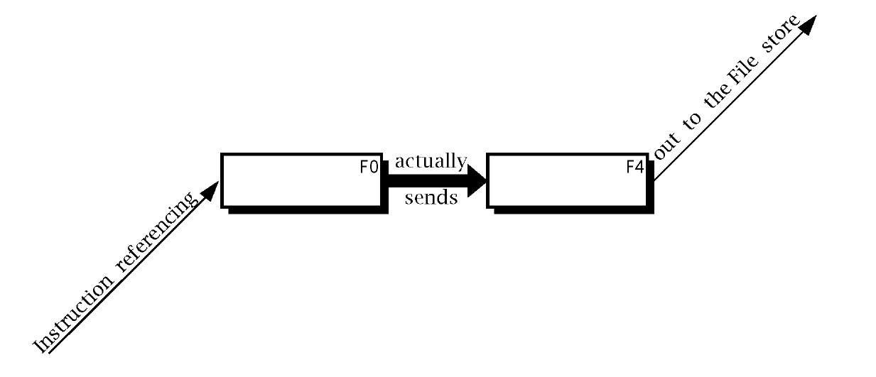
In our BASIC computer the File Select Register (FSR) is implemented as File4 in the File store. The indirect mechanism is evoked when the dummy address File 0 (there is no physical file at location 0 in the Data store) is used for the operand address, as shown in Fig. 3.6.7 Thus, for example, if the contents of File 4 happened to be 20h then:
will effectively copy the contents of W out to File 20h.
This seems rather an obscure way of doing things, but by way of a justification let us revisit our array clearing example of Program 3.1. Repeating the same thing 52 times on successive file locations is a dubious way of doing this. Why not use a pointer into the array, and increment this pointer each time we do a Clear? That is, rather than using a constant address for the destination operand use a variable effective address.
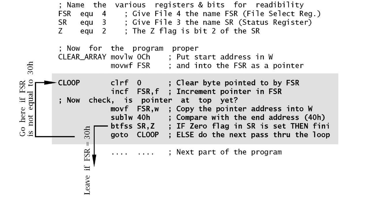
Program 3.2 follows the scheme by folding the linear structure of the previous program into a loop, shown shaded. The execution path keeps circulating around the clrf instruction, which is ‘walked’ through the array of files by advancing the pointer in File4, the FSR, on each pass through the loop. Eventually the pointer moves beyond the desired range and the program then exits the loop and continues onto the next section of code.
Fig. 3.6 The indirect mechanism.
Program 3.2 has many new features, especially as we haven’t yet reviewed the instruction set.
Program 3.2 Clearing a block of files using a repeating loop.
Phase 1
From the point of view of readability, variables, registers and individual status and control bits should be given a relevant name. For example, btfss STATUS,Z (Bit Test File Skip if Set) which checks the Z flag (bit2 in File 3) and skips the following instruction if set (that is the outcome of the previous instruction is zero) can be written in two ways; both of which are functionally identical:
Obviously the latter is preferable. Although this might seem to be a cosmetic exercise, clarity reduces the chance of error and makes debugging and subsequent alteration easier. Realistic programs, rather than the code fragment illustrated here, use many variables and register bits, so lucidity is all the more important.
The three header lines of our program illustrate the means whereby the programmer tells the assembler translator program to substitute numbers for names. For example the line:
states that when the programmer uses the name FSR as an operand, it is to be substituted by the number 4 (that is File 4). The equ directive means "equivalent to". A directive is a pseudo instruction in that it does not usually produce actual machine code but rather is a means of passing information from the programmer to the assembler program.
Phase 2
The first two proper instructions initialize the File Select Register to point to the first byte to be cleared, by moving the constant 0Ch into the Working register and then out to File 4. Nearly all loop instructions involve some setting up before entry.
Phase 3
The key Clear instruction uses the File Indirect address mode by specifying the phantom File 0 as the destination address. This line has a label associated with it called CLOOP. The assembler knows that this is a label and not an instruction as it appears in the leftmost column of the source file. Lines without labels should begin with an indent of at least one space.
Each pass around the loop involves an incrementation of the pointer. This is done by using the incf FSR,f instruction to increment the FSR file. Notice that the destination here is specified as a file and not the W register.
Phase 4
Unless you wish to go round the loop forever, we need a mechanism to eventually exit. In our case this is done by comparing the contents of the FSR pointer file with the constant 40h, that is with one over the top target file 3Fh. The comparison mechanism is to copy the contents of the FSR pointer into W and then subtract W from the literal 40h using sublw 40h. If they are equal then the Z flag will be set and in this event the next btfss instruction will skip over the following goto LOOP instruction, out of the loop. Until this happens, the goto instruction will move the execution back up to the beginning of the loop and the process is repeated with the FSR advanced to point to the next file to be cleared.
All together our loop version takes eight machine instructions against the 52 of the linear equivalent. However, it does take longer to execute as the six instructions in the loop are repeated 52 times!
Absolute
The goto instruction forces the execution to directly transfer to the specified address by simply overwriting the Program Counter with the effective address – for example goto 145h puts 145 h into the PC. It contrasts with the various Skip instructions which simply branch over the following instruction, wherever they are encountered. This latter type of branch is called relative, as opposed to the absolute transfer of execution used by the goto instruction.
Having covered the address modes, let us look briefly at the instruction set in Table 3.1. Instructions have been divided into four groups as follows.
Arithmetic
This covers the Addition, Subtraction, Incrementation, Decrementation and Clearing operations. Addition is possible between data in W and out in the File store, with the sum being placed either in the same file or in W. Similarly subtraction of W from a file is implemented, with the difference being placed in the same file or W. Both instructions come in a literal version, where W is added to/subtracted from an 8-bit constant, with the outcome remaining in the Working register. Notice that in the latter case the variable in W is subtracted from the literal rather than the more obvious subtraction of the literal from W.
The contents of any file can be incremented or decremented using incf and decf respectively. The outcome is usually put back into the file but the Working register can alternatively be specified as the destination.
Any file can be cleared with clrf, for instance clrf 20h. In the same manner the Working register can be zeroed with clrw.
Movement
This category of instructions copy a datum from source to destination. In all cases the contents of the source remains unaltered. movf reads (loads) a byte from the File store, usually into the Working register; eg. movf 20h,w. It is possible to specify the seemingly useless operation of copying a file’s datum on top of itself, such as in move 20h,f. However,this does have the side effect of setting the Z flag if the datum is zero but in any case not altering a file’s contents. This can be used to implement a Test for Zero operation.
Other instructions in this category write (store) the contents of W out into the File store (eg. movwf 20h copies W into File 20h) or a literal into W (eg. movlw 6 puts the constant 06h into W).
Logic
The comf instruction inverts (complements or NOTs) all bits in the specified file. For example:
The andwf instruction bitwize ANDs the contents of the Working register to that of a specified file, with the outcome being either in W or in the file. For example:
It is also possible to AND a constant to W by using the andlw variant.
Whilst the AND operation can be used to zero (mask) any bit or bits in the specified file, the Inclusive-OR equivalent instructions can set to one any bit or bits in the destination. For example, ORing W with the literal 10000000b (80h):
remembering from Fig. 1.3 that ORing with a logic 1 always results in a logic 1 outcome and ORing with zero does not alter the original data, leads to the outcome that the most significant bit position of W is set and the other bits remain unaltered.
The xorwf and xorlw instructions provide for the eXclusive-OR operation.Thus, for example if we wished to invert both bits 0 and 7 of W:
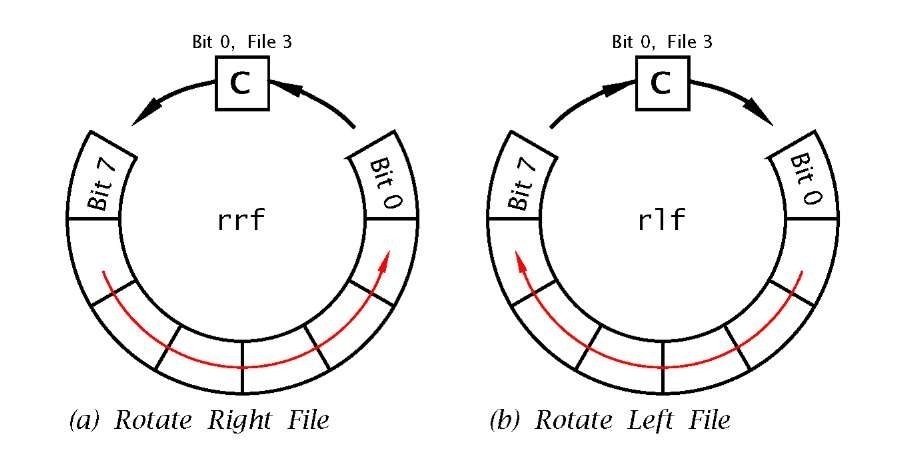
Two instructions are provided that can shift the contents of any file once left or right, with the outcome either remaining in the file or appearing in the W register. As shown in Fig. 3.7 the outgoing bit (bit 7 for rlf f,d and bit 0 for rrf f,d) is placed in the C flag, whilst the incoming bit at the opposite end is the previous value of C. Because of this ‘circular’ action these instructions are said to implement a Rotate data through the Carry operation.
Skip and Jump
These instructions alter the state of the Program Counter, effectively interrupting the progressive flow of the program and causing processing to branch to another point in the code. The simplest of these instructions is goto. This overwrites the PC with the absolute destination address. For instance, goto 200h will change the PC to 200h and cause the program flow to ‘jump’ to whatever instruction is located at this address. Another example is instruction 8 in Program 3.2 where execution jumps back up to the beginning of the loop at address CLOOP.
The goto instruction causes an unconditional absolute jump in the program flow, implementing a ‘Jump Always’ operation. The remaining four instructions are conditional in that the smooth program progression is interrupted only if the outcome matches the specified state. For instance decfsz decrements the specified file contents and if and only if the outcome is zero the following instruction is skipped over.
Four instructions in our set come into this category, in that they increment the PC if some condition is fulfilled. Remembering that each instruction occupies one word in Program memory, incrementing the PC is equivalent to skipping over the following instruction. This relative skip-over action is in contrast with the absolute always jump to the specified address action of the goto instruction. The four relative instructions are:
btfsc
Bit Test File & Skip if Clear by-passes the next instruction if the specified bit in the file in question is zero. For example btfsc 3,02h skips if bit 2 in File 3 is clear.
Bit Test File & Skip if Set by-passes the next instruction if the specified bit in the file in question is one. For example btfss 3,02h skips if bit 2 in File 3 is one.
DECrement File & Skip if outcome is Zero subtracts one from the specified file and by-passes the next instruction if the outcome is zero. For example decfsz 30h,f skips if the content of 30h once decremented is zero. The decremented value is placed back in the file in this example but W is an alternative destination, as in decfsz 30h,w.
INCrement File & Skip if outcome is Zero adds one to the specified file and by-passes the next instruction if the outcome is zero. For example incfsz 30h,f skips if the content of 30h once incremented is zero. The incremented value is placed back in the file in this example but W is an alternative destination, as in incfsz 30h,w.
Actually the Program Counter is located in the Data store as File 2. Thus manipulating this file can implement a computed relative skip. For example:
As more sophisticated example of the use of conditional Skip instructions and the absolute goto instructions, consider the problem of repeating a sequence 16 times. The most efficient approach to the coding is to construct a program loop and keep track of the number of times the processor executes the encapsulated instructions. In the following listing File 22h is used as the counter, initialised to 16 before the loop is entered. At the end of the sequence the count is decremented using decfsz and normally the next instruction, which transfers the PC back up to the start of the loop, is executed. However, eventually the count reaches zero and the goto LOOP instruction is skipped over, with execution consequently exiting the loop. Traditionally the potentially skipped over instruction is shown indented as a matter of style.
The incfsz instruction works in a similar manner, but for an up count, skipping when the target file overflows FF — 00h. As an exercise, repeat the example but using incfsz in place of decfsz.The ++(f) and–(f) rtl symbology used to describe the incfsz and decfsz instructions indicate that the contents of the designated file is augmented or decremented before testing for zero.
The other set of skip instructions uses the state of any bit b in any file to force a conditional skip. Thus if it is desired that the program transfers to an instruction located at label REAL_TIME if bit 2 of File 0Bh is logic 1, then we can use the btfsc (Bit Test File & Skip on Clear) instruction thus:
In Table 3.1 the rtl language description of this instruction is given as b==0?PC++:PC, which can be read as:
1. Is the specified bit (b) equivalent to (==) zero (?).
2. If true then increment the PC (PC++), that is skip.
3. Else it is false, so leave the PC alone.
Similarly the — rtl operator is used to indicate decrementation.
Examples
Example 3.1
Write a program to add the byte contents in File memory called NUM1 (File 20h) to NUM2 (File 21 h). The outcome is to be in SUM_H and SUM_L (File 22h and File 23h respectively) in the order high:low byte.
Solution
The three instructions to implement this are shown in Program 3.3. The variable NUM1 is simply fetched down into the Working register and then added to variable NUM2. The outcome of this is then copied into the sum byte SUM_L.
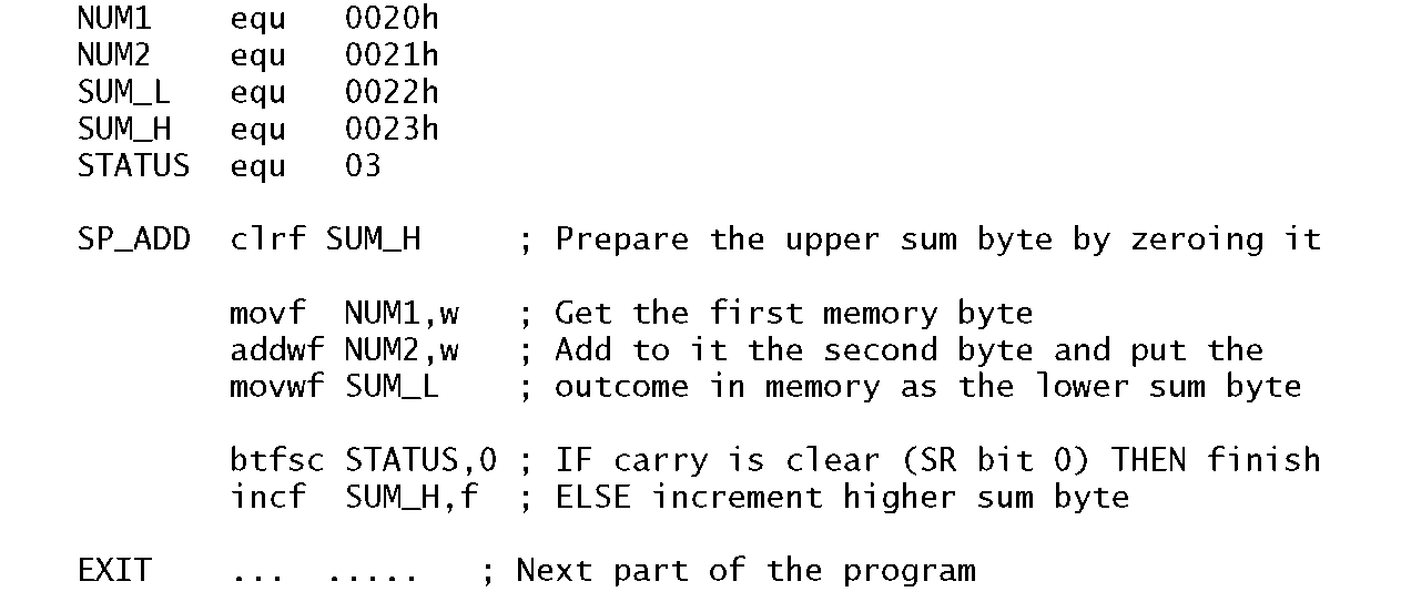
Of course this will only work if the outcome of the addition can fit into a single byte; that is no more than FFh (255d). If, for example, both NUM1 and NUM2 were FFh, then the outcome would be 1FFh. Thus we need to reserve two bytes for the sum; an upper byte and a lower byte; named SUM_H and SUM_L in Program 3.4 in File 22h and File 23h respectively. In this implementation we simply zero the upper byte of the sum in advance, and after the addition skip around the Increment of instruction 6 if the Carry flag (bit 0 in File register 3) is Clear (Bit Test File and Skip on Clear). The upper sum byte can only ever be either 00h or 01 h.
Program 3.3 Simple single-precision addition of two byte variables.
Program 3.4 A more accurate single-precision addition of two byte variables.
Example 3.2
Write a program routine that will add two 16-bit numbers giving a 17bit sum. The augend is located in the two memory locations F20h:F21 h in the order high:low byte thus![tmp18267_thumb[2][2] tmp18267_thumb[2][2]](http://what-when-how.com/wp-content/uploads/2011/06/tmp18267_thumb22_thumb.png) The addend is similarly situated
The addend is similarly situated![tmp18268_thumb[2][2] tmp18268_thumb[2][2]](http://what-when-how.com/wp-content/uploads/2011/06/tmp18268_thumb22_thumb.png) The sum is stored as three bytes in the order high:middle:low thus
The sum is stored as three bytes in the order high:middle:low thus![tmp18269_thumb[2][2] tmp18269_thumb[2][2]](http://what-when-how.com/wp-content/uploads/2011/06/tmp18269_thumb22_thumb.png)
![tmp18252_thumb[2][2] tmp18252_thumb[2][2]](http://what-when-how.com/wp-content/uploads/2011/06/tmp18252_thumb22_thumb.png)


![tmp18255_thumb[2][2] tmp18255_thumb[2][2]](http://what-when-how.com/wp-content/uploads/2011/06/tmp18255_thumb22_thumb.png)
![tmp18256_thumb[2][2] tmp18256_thumb[2][2]](http://what-when-how.com/wp-content/uploads/2011/06/tmp18256_thumb22_thumb.png)
![tmp18257_thumb[2][2] tmp18257_thumb[2][2]](http://what-when-how.com/wp-content/uploads/2011/06/tmp18257_thumb22_thumb.png)
![tmp18258_thumb[2][2] tmp18258_thumb[2][2]](http://what-when-how.com/wp-content/uploads/2011/06/tmp18258_thumb22_thumb.png)
![tmp18259_thumb[2][2] tmp18259_thumb[2][2]](http://what-when-how.com/wp-content/uploads/2011/06/tmp18259_thumb22_thumb.png)
![tmp18260_thumb[2][2] tmp18260_thumb[2][2]](http://what-when-how.com/wp-content/uploads/2011/06/tmp18260_thumb22_thumb.png)

![tmp18262_thumb[2][2] tmp18262_thumb[2][2]](http://what-when-how.com/wp-content/uploads/2011/06/tmp18262_thumb22_thumb.png)
![tmp18263_thumb[2][2] tmp18263_thumb[2][2]](http://what-when-how.com/wp-content/uploads/2011/06/tmp18263_thumb22_thumb.png)
![tmp18264_thumb[2][2] tmp18264_thumb[2][2]](http://what-when-how.com/wp-content/uploads/2011/06/tmp18264_thumb22_thumb.png)


