ABSTRACT
An experimental-numerical hybrid method for determining stress components in photoelasticity is proposed in this study. Boundary conditions for a local finite element model, that is, tractions along boundaries are inversely determined from photoelastic fringes. The tractions can be obtained by the method of linear least-squares from both principal stress difference and principal direction. On the other hand, the tractions can also be determined only from the principal stress difference if nonlinear least-squares is used. After determining the boundary conditions for the local finite element model, the stresses can be obtained by finite element direct analysis. The effectiveness of the proposed method is validated by analyzing the stresses in a perforated plate under tension. Results show that the boundary conditions of the local finite element model can be determined from the photoelastic fringes and then the individual stresses can be obtained by the proposed method.
INTRODUCTION
Optical methods in experimental stress analysis such as photoelasticity, thermoelasticity and a wide variety of interferometric methods are useful and valuable techniques because they provide whole-field information on a specimen surface or the area of interest. However, it is sometimes difficult to extract desired quantities from the quantities obtained by these methods. For example, moire interferometry provides surface displacements and then strains are obtained by differentiating the displacements spatially. However, the differentiation of measured displacements has the difficulties that the errors in the measured values give rise to even greater errors in their derivatives. Thus, various studies have been performed to obtain strains from measured displacements [1-4].
In the case of photoelasticity, it is well known that the fringe patterns represent the principal stress difference and the principal direction, and thus the stress components themselves cannot be obtained directly. Conventionally, a method based on the equilibrium equation or compatibility equation such as a shear difference method has been used for the stress separation in photoelasticity [5,6]. Several stress separation techniques based on the conventional methods have been developed [7-9]. The major drawback of the conventional methods is that the stresses obtained by these methods usually suffer from error accumulation arising by finite difference approximation. On the other hand, various techniques for determining stress components have also been reported. Patterson and coworkers [10,11], and Sakagami et al. [12] developed a hybrid method of photoelasticity and thermoelasticity. In this method, the difference and the sum of principal stresses are measured separately, and then, they are combined for obtaining stress components. The difference and the sum of principal stresses can also be obtained by combining photoelasticity and interferometry [13-16]. The disadvantage of the hybrid methods of photoelasticity and another experimental method is that the measurement can be complicated. On the other hand, several hybrid methods with theoretical analysis or numerical analysis, and inverse analysis methods have also been proposed for the stress separation. Chang et al. [17] determined the coefficients of Airy stress function from photoelastic fringes for determining stresses. Berghaus [18] proposed a hybrid method with a finite element method. In this method, displacement boundary condition along the axis of symmetry and free boundary for a finite element method is determined by photoelasticity. Hayabusa et al. [19] and Chen et al. [20] proposed a hybrid method with a numerical method such as a boundary element method. They determined boundary conditions by inverse analysis from photoelastic fringes and then stresses are determined by direct analysis.
The stress separation can be performed by the methods mentioned above. Particularly it can be considered that the use of numerical methods such as a finite element method or a boundary element method for stress separation is useful because the data processing is easy and full-field stresses and strains can be obtained easily. However, inverse boundary value problems are often ill-posed. Therefore, various additional techniques should be introduced to the inverse analysis for obtaining stable and accurate results. In the present study, an alternative and simple hybrid method for stress separation in photoelasticity is proposed. Boundary conditions for a local finite element model, that is, tractions along the boundaries are determined by inverse analysis from photoelastic fringes. Two algorithms are presented. One is linear algorithm that the tractions are determined from the principal stress difference and the principal direction using the method of linear least-squares. In another algorithm, on the other hand, the tractions are determined only from the principal stress difference using nonlinear least-squares. After determining the tractions, the stress components are obtained by finite element direct analysis. The effectiveness of the proposed method is validated by analyzing the stresses around a hole in a plate under tension. Results show that the boundary conditions of the local finite element model can be determined from the photoelastic fringes and then the stresses can be obtained by the proposed method.
INVERSION OF BOUNDARY CONDITIONS
Basic Principle
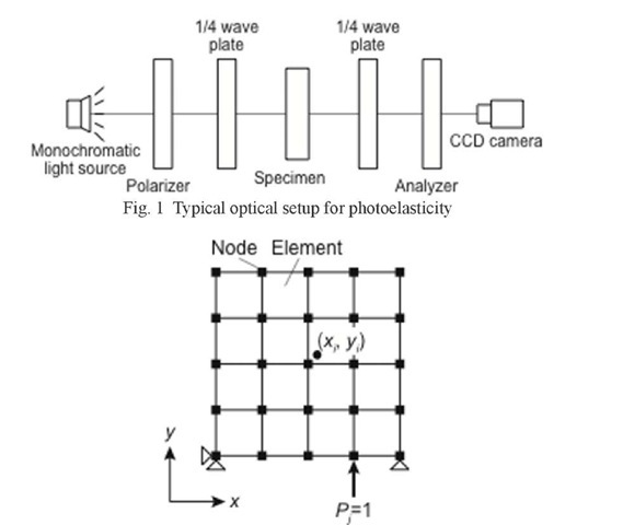
Figure 1 shows a typical optical setup for photoelasticity, that is, a circular polariscope. A birefringent specimen is placed in the polariscope, and then, photoelastic fringes are appeared when the specimen is loaded. The angle 9 of the principal axis of the specimen is interpreted as the principal direction, i.e., the isoclinic parameter. Similarly, the retardation 8 of the specimen, that is, the isochromatic parameter is related to the principal stress difference as [21]
where fs is the material fringe value, h is the thickness of a specimen, and cti and ct2 express the principal stresses, respectively. Various techniques such as a phase-stepping method can be used for obtaining the isochromatic and isoclinic parameters [22-25]. Therefore, the principal stress difference and the principal direction are obtained in the region of interest or the whole field of the specimen by introducing one of the data acquisition and processing techniques.
In a finite element method, on the other hand, it can be considered that the reasonably accurate stress distributions are obtained when the appropriate boundary conditions are given, provided that appropriate finite element model is used and material properties are known. In the proposed method, therefore, the boundary conditions of the region for analysis, that is, the tractions along the boundaries, are inversely determined from photoelastic fringes. Then, the stresses are determined by finite element direct analysis by applying the computed boundary conditions.
Figure 2 schematically shows a two-dimensional finite element model of the region for analysis. The displacements of some nodes are fixed so that the rigid body motion is not allowed. Then, a unit force along one of the direction of the coordinate system is applied to a node at the boundary of the model. That is, the finite element analysis is performed under the boundary condition of the unit force on the boundary. The analysis is repeated by changing the direction of the unit force and the node at which the unit force is applied. The stress components at a point (xi, y) for the applied unit force![]() are represented as
are represented as![]() Here,
Here,![]() is the data index, j is the index of the applied force, M is the number of the data points, and N is the number of the forces to be determined at the nodes along the boundary of the model. The stress components
is the data index, j is the index of the applied force, M is the number of the data points, and N is the number of the forces to be determined at the nodes along the boundary of the model. The stress components ![]() at the point (x, y) under the actual applied forces
at the point (x, y) under the actual applied forces![]() > can be expressed using the principle of superposition as
> can be expressed using the principle of superposition as
where the summation convention is used. That is, for example,
Fig. 2 Finite element model with boundary condition of unit force
In equation (2), Fj is the nodal forces along the boundary. Therefore, the tractions along the boundaries are determined and subsequent stress analysis can be performed if the values of Fj are determined.
Linear Algorithm
From the principal stress difference![]() and the principal direction 9 obtained by photoelasticity, the normal stress difference
and the principal direction 9 obtained by photoelasticity, the normal stress difference![]() and the shear stress xxy are obtained as
and the shear stress xxy are obtained as
Therefore, the relationships between the values obtained by photoelasticity and the nodal forces Fj along the boundary can be expressed as
where (ctx – ay)i and (xxy)i express the normal stress difference and the shear stress at the point (x,, y) obtained by photoelasticity. Equation (4) expresses linear equations in the unknown coefficients Fj. For numerous data points, an over-determined set of simultaneous equations is obtained. In this case, the nodal forces Fj along the boundary can be estimated using linear least-squares as
where F, A and S are the nodal force, stresses under the boundary condition of the unit force and the values obtained by pho-toelasticity, respectively. They are expressed as
After determining the nodal force F along the boundary using equation (5), the stress components can be obtained by the finite element direct analysis by using the nodal force F as the boundary condition.
Nonlinear Algorithm
As is well known, it is difficult to obtain the accurate values of the principal direction by photoelasticity. The measured principal direction is sometimes affected by the isochromatics and the accuracy of quarter-wave plates. In order to obtain accurate values of the principal direction, various techniques have been proposed [26,27]. Because the accurate values of the principal direction cannot always be obtained, a method for determining the boundary condition without the principal direction is also described below.
The principal stress difference is expressed using the stress components as
Therefore, the relationship between the experimentally obtained values of the principal stress difference and the nodal forces Fj along the boundary can be expressed as
where![]() is the principal stress difference obtained by photoelasticity at the point (xi, yi). Equation (7) is nonlinear in the unknown parameters Fj. To solve these parameters, an iterative procedure based on Newton-Raphson method is employed. Equation (7) is rewritten as
is the principal stress difference obtained by photoelasticity at the point (xi, yi). Equation (7) is nonlinear in the unknown parameters Fj. To solve these parameters, an iterative procedure based on Newton-Raphson method is employed. Equation (7) is rewritten as
A series of iterative equations based on Taylor’s series expansions of equation (8) yields the following equations.
where subscript k denotes the kth iteration step, and![]() are the corrections to the previous estimation of Fi, …, FN.
are the corrections to the previous estimation of Fi, …, FN.
The desired results![]() yield the following simultaneous equations with respect to the corrections.
yield the following simultaneous equations with respect to the corrections.
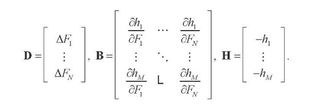
The solution of equation (10) in the least-squares sense is
In that equation,
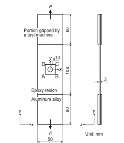
Fig. 3 Perforated plate specimen used for verifying the proposed method
The solution of the matrix equation gives the correction terms for prior estimates of the coefficients. Accordingly, an iterative procedure must be used to obtain the best-fit set of coefficients. Then, the estimates of the unknowns are revised. This procedure is repeated until the corrections become acceptably small. After determining the nodal forces along the boundary, the stress components can be obtained by the finite element direct analysis by using the nodal forces as the boundary condition. That is, the stress separation can be performed. It is noted that because the method described here uses only the principal stress difference, the sign of the applied forces along the boundary cannot be determined. In other words, the proposed nonlinear algorithm cannot judge whether the traction is tension or compression. Therefore, the appropriate initial values should be provided for the calculation of the nonlinear least-squares.


