Abstract
Strain localization and dislocation pattern formation are typical features of plastic deformation in metals and alloys. Glide and climb dislocation motion along with accompanying production/annihilation processes of dislocations lead to the occurrence of instabilities of initially uniform dislocation distributions. These instabilities result into the development of various types of dislocation micro-structures, such as dislocation cells, slip and kink bands, persistent slip bands, labyrinth structures, etc., depending on the externally applied loading and the intrinsic lattice constraints. The Walgraef-Aifantis (WA) (Walgraef and Aifanits, J. Appl. Phys., 58, 668,1985) model is an example of a reaction-diffusion model of coupled nonlinear equations which describe 0 formation of forest (immobile) and gliding (mobile) dislocation densities in the presence of cyclic loading. This paper discuss two versions of the WA model, the first one comprising linear diffusion of the density of mobile dislocations and the second one, with nonlinear diffusion of said variable. Subsequently, the paper focus on a finite difference, second order in time Cranck-Nicholson semi-implicit scheme, with internal iterations at each time step and a spatial splitting using the Stabilizing, Correction (Christov and Pontes, Mathematical and Computer 0, 35, 87, 2002) for solving the model evolution equations in two dimensions. The discussion on the WA model and on the numerical scheme was already presented on a conference paper by the authors (Pontes et al., AIP Conference Proceedings, Vol. 1301 pp. 511-519, 2010). The first results of four simulations, one with linear diffusion of the mobile dislocations and three with nonlinear diffusion are presented. Several phenomena were observed in the numerical simulations, like the increase of the fundamental wavelength of the structure, the increase of the walls height and the decrease of its thickness.
Keywords: Finite differences, pattern formation, dislocation patterns, fatigue PACS: 05.45.-a, 02.70.Bf, 62.20.me, 46.70.-p
THE WALGRAEF-AIFANTIS (WA) MODEL
In the spirit of earlier dislocation models derived for example by Ghoniem et al. (1990) [1] for creep, or by Walgraef and Aifantis (1985 [2], 1986 [3], 1997 [4]), by Schiller and Walgraef (1988 [5]), and by Kratochvil (1979) [6], for dislocation micro-structures formation in fatigue, the dislocation population is divided into static dislocations, which may result from work hardening and consist in the nearly immobile dislocations of the "forest", of sub-grains walls or boundaries, etc., and the mobile dislocations which glide between these obstacles.
The essential features of the dislocation dynamics in the plastic regime are, on the one side, their mobility, dominated by plastic flow, but which also includes thermal diffusion and climb, and their mutual interaction process, the more important being (Mughrabi et al, 1979 [7]):
• Multiplication of static dislocations within the forest;
• Static recovery in the forest via static-static annihilation processes;
• Freeing of static dislocations: when the effective stress increases and exceeds some threshold, it disturbs the local structure of the forest and, in particular, destabilize dislocation clusters which decompose into mobile dislocations. The freeing of forest dislocations occurs with a rate f5, which depends on the applied stresses and material parameters;
• Pinning of mobile dislocation by the forest. Effectively, mobile dislocations may be immobilized by the various dislocation clusters forming the forest. The dynamical contribution of such processes is of the form![]() is the pinning rate of a mobile dislocation by a cluster of n static ones. The Walgraef-Aifantis (WA) model considers n = 2.
is the pinning rate of a mobile dislocation by a cluster of n static ones. The Walgraef-Aifantis (WA) model considers n = 2.
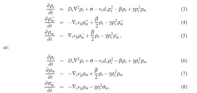
The resulting dynamical system may then be written as:
where time is measured in number of cycles of loading, Ds represents the effective diffusion within the forest resulting from the thermal mobility and climb and Dm represents the effective diffusion resulting from the glide of mobile dislocations between obstacles (D m ^ Ds). The coefficient dc is the characteristic length of spontaneous dipole collapse. f5 is the rate of dislocation freeing from the forest and is associated with the de-stabilization of dislocation dipoles or clusters under stress. Numerical dislocation dynamics simulations show that in BBC crystals, for 0, there is a critical value of external applied stresses above which dislocation dipoles become unstable. This value is a decreasing function of the distance between dipole slip lines. If the forest may be considered as an ensemble of dipoles with a mean characteristic width, the 0 stress for de-stabilization, or freeing, Of, could be extracted from such simulations. More extended numerical analysis could include higher order dislocation clusters and provide the dependence of the threshold stress on the forest dislocation 0. The freeing rate should thus be zero below the freeing threshold, and an increasing function of the applied stress above it. Hence,![]() being a phenomenological parameter.
being a phenomenological parameter.
THE MODIFIED WA MODEL: EFFECT OF GRADIENT TERMS
The approximation of mobile dislocation diffusion is controversial and may be addressed. To do so, the mobile dislocation density, pm is divided into two 1 representing the dislocation gliding in the direction of the Burgers vector![]() and in the opposite one
and in the opposite one![]()
For crystals with well-developed forest density, and oriented for single slip, we now write (with vg oriented along the x direction):
where![]() is the density of geometrically necessary dislocations. This variables evolves faster than the other two and may be adiabatically eliminated, leading to the following system, which includes a nonlinear diffusion term in the equation of pm:
is the density of geometrically necessary dislocations. This variables evolves faster than the other two and may be adiabatically eliminated, leading to the following system, which includes a nonlinear diffusion term in the equation of pm:
THE NUMERICAL SCHEME FOR SOLVING THE WA MODEL
In order to solve the modified WA model, we use a numerical scheme based on a one proposed by Christov and Pontes (2002). Equations (9) and (10) are solved numerically in two-dimensional rectangular domains, through the finite difference method, using a grid of uniformly spaced points, a second order in time Crank-Nicholson semi-implicit method with internal iterations at each time step, due to the nonlinear nature of the implicit terms. The proposed scheme is splitted in two equations using the Stabilizing Correction scheme (Christov and Pontes, 2002 [8], Yanenko, 1971 [9]). The first half-step comprises implicit derivatives with respect to x and explicit derivatives with respect to y. In the second half-step,n the derivatives with respect to y are kept implicit and those with respect to x are explicit. The splitting scheme is shown to be equivalent to the original one.
The target scheme
The target second order in time, Crank-Nicholson semi-implicit scheme is:
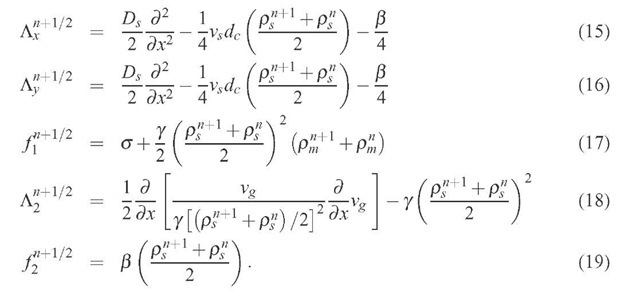
where n is the number of the time step. Upon including the 1/2 factor in the operators
we obtain:
The operators
and the functions
are defined as:
Internal iterations
as well as the functions
and
contain terms in the new stage, we do internal iterations at each time step,according to:
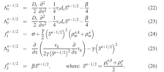
where the superscript (n, k + 1) identifies the "new" iteration, (n, k) and n stand for the values obtained in the previous iteration and in the previous time step, respectively. The operators
and the functions
are redefined as:
The iterations proceed until the following criteria is satisfied:
in all grid points, for a certain K. Then the last iteration gives the value of the sought functions in the "new" time step,
The splitting of the ps equation
The splitting of Eq. (20) is made according to:
In order to show that the splitting represents the original scheme, we rewrite Eqs. (27) and (28) in the form:
where E is the unity operator. The intermediate variable ps is eliminated by applying the operator to the second equation and summing the result to the first one:
This result may be rewritten as:
or either:
A comparison with Eq. (20) shows that Eq. (33) is actually equivalent to the first one except by the defined positive operator having a norm greater than one,
which acts on the term . This means that this operator does not change the steady state solution. Furthermore, since ||5|| > 1 the 3 scheme is more stable than the original scheme.
Spatial discretization
The grid is "staggered" and the discretization of the diffusive term of Eq. (10) is made according to the following formula, which preserves the conservation law implicit in the divergence:
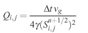
Upon defining:
we replace the diffusive term of pm by:
The diffusive terms of Eq. (9) are written in discrete form by using the usual three points centered formula, of second order. Neumann boundary conditions are used in the integration of the WA model, with derivatives in the direction perpendicular to the walls equal to zero. The algebraic linear systems were solved using a routine with 0 elimination and pivoting, written by one of us (CIC).
RESULTS
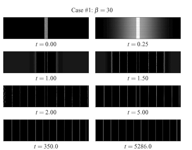
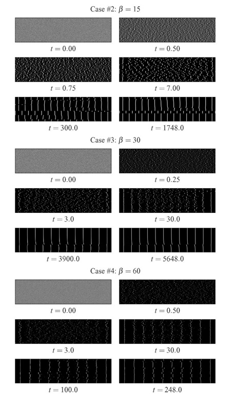
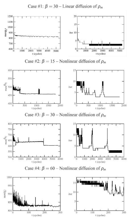
We present the results of four simulations in a box with dimensions 25 x 5 jim. system parameters are: vs = 1 jmcm1, dc = 2.5-2jm, Ds = 3 x 10⁻³jm2cy-1 (linear case), vg = 102jmcy-1, Y = 2 x 10⁻², a = 250jm-2cy-1. The simulations were run with a time step of 2.5 x 10⁻³cy. Case #1 refers to system with linear diffusion of pm, initial condition consisting of a central stripe with random values of ps and zero everywhere else. Cases #2 to 4 refer to systems with nonlinear diffusion of pm, initial condition consisting of the uniform base state pm = y2a/ (p2vsdc) and ps = p/ (Ypm) and bifurcation parameter p = 15, 30 and 60 respectively (see Tab. 1). Figs. 1 and 2 present the time evolution of ps for the four cases considered. Fig. 3 show the time evolution of the maximum of ps and the computional effort, given by the number of internal iterations per time step.
TABLE 1. Main data of the four simulations presented
|
Case |
Diffusion of pm |
Initial Cond. |
P |
Grid points |
Walls |
|
1 |
linear |
Vertical band |
30 |
3000 x 750 |
12 |
|
2 |
nonlinear |
random |
15 |
3000 x 750 |
15 |
|
3 |
nonlinear |
random |
30 |
3000 x 750 |
12 |
|
4 |
nonlinear |
random |
60 |
4000x 1000 |
10 |
FIGURE 1. Time evolution of Case #1 of dislocation pattern formation in a rectangular stripe with 20 x 5 jm, starting from a vertical stripe with random distribution of ps and pm and linear diffusion of pm.
FIGURE 2. Time evolution of Cases #2 to 4 of dislocation pattern formation in a rectangular stripe with 20 x 5 jum, starting from a random distribution of ps and pm and nonlinear diffusion of pm.
FIGURE 3. Time evolution curves of max(ps) x t and of the computational effort (number of internal iterations per step) for the four cases considered.
DISCUSSION
A number of phenomena emerge from the numerical simulations presented, the main ones being:
1. The increase of the bifurcation parameter p results in strucuteres with larger wavelength. The walls height increases and its thickness decreases with p. Thinner walls required the use of finer numerical meshes, resulting in greater computational effort (Case #4, with p = 60);
2. The height of the walls decreases as pattern defects are eliminated. The pattern evolution accelerates at the moments where defects are eliminated, Higher local crests appear at these moments. The computational effort, measured by the number of internal iterations at each time step increases (see Fig. 3);
3. Increasing the bifurcation parameter p from 15 to 30 accelerates the pattern formation. Further increasing p to 60 results in longer transients, possibly due to the disordering effect of higher forcing;
4. The movement of small pieces of dislocation walls along the x direction is enhanced by the nonlinear diffusion of pm.
CONCLUSIONS
We presented a finite differences second-order in time scheme for solving reaction-diffusion equations in two dimensions. Second order was achieved by performing internal iterations at each time step. The scheme was implemented in a mesoscopic two-equations model proposed by Walgraef and Aifantis (1985) [2] to model dislocation dynamics in materials subjected to cyclic loading. Dislocations are grouped in two variables, the first one consisting of a density of immobile or static dislocations, ps, (forest of dislocations). The second group consists of mobile dislocations that move along the forest of static ones and are grouped in a density pm. The density of static dislocations diffuses along both directions, whereas the mobile dislocations present a nonlinear diffusion along one of the directions only. The scheme of Stabilizing Correction was used for the splitting of the evolution equation of ps (Yanenko,1971 [9], Christov and Pontes, 2002 [8], Pontes et al., 2010 [10]).
Several phenomena were observed in the numerical simulations, like the increase of the fundamental wavelength of the structure, the increase of the walls height and the decrease of its thickness. More complete results and discussion will be given in a forthcoming paper.

