In topic 5 we saw that the 3-phase stator windings of an induction motor produce a sinusoidal rotating magnetic field in the air-gap. The speed of rotation of the field (the synchronous speed) was shown to be directly proportional to the supply frequency, and inversely proportional to the pole number of the winding. We also saw that in the induction motor the rotor is dragged along by the field, but that the higher the load on the shaft, the more the rotor has to slip with respect to the field in order to induce the rotor currents required to produce the torque. Thus although at no-load the speed of the rotor can be close to the synchronous speed, it must always be less; and as the load increases, the speed has to fall.
In the synchronous motor, the stator windings are exactly the same as in the induction motor, so when connected to the 3-phase supply, a rotating magnetic field is produced. But instead of having a cylindrical rotor with a cage winding, the synchronous motor has a rotor with either a d.c. excited winding (supplied via sliprings), or permanent magnets, designed to cause the rotor to ‘lock-on’ or ‘synchronise with’ the rotating magnetic field produced by the stator. Once the rotor is synchronised, it will run at exactly the same speed as the rotating field despite load variation, so under constant-frequency operation the speed will remain constant as long as the supply frequency is stable.
As previously shown, the synchronous speed (in rev/min) is given by the expression

where f is the supply frequency and p is the pole number of the winding. Hence for two-, four- and six-pole industrial motors the running speeds
on a 50 Hz supply are 3000, 1500 and 1000 rev/min, while on a 60 Hz supply they become 3600, 1800 and 1200 rev/min, respectively. At the other extreme, the little motor in a central heating timer with its cup-shaped rotor with 20 axially projecting fingers and a circular coil in the middle is a 20-pole reluctance synchronous motor that will run at 300 rev/min when fed from 50 Hz mains. Users who want speeds different from these will be disappointed, unless they are prepared to invest in a variable-frequency inverter.
We discussed a similar mechanism whereby the rotor locked onto a magnetic field in connection with the stepping motor (see topic 9), but there the field proceeds in a stepwise fashion, rather than smoothly. With the synchronous machine we again find that, as with the stepper, there is a limit to the maximum (pull-out) torque which can be developed before the rotor is forced out of synchronism with the rotating field. This ‘pull-out’ torque will typically be 1.5 times the continuous rated torque, but for all torques below pull-out the steady running speed will be absolutely constant. The torque-speed curve is therefore simply a vertical line at the synchronous speed, as shown in Figure 10.1. We can see from Figure 10.1 that the vertical line extends into quadrant 2, which indicates that if we try to force the speed above the synchronous speed the machine will act as a generator.
The mains-fed synchronous motor is clearly ideal where a constant speed is essential, and also where several motors must run at precisely the same speed. Examples where 3-phase motors are used include artificial fibre spinning lines, and film and tape transports. Small single-phase reluctance versions are used in clocks and timers for washing
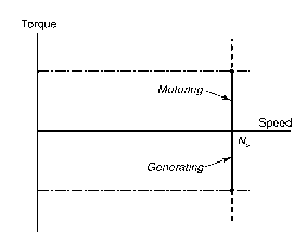
Figure 10.1 Steady-state torque-speed curve for a synchronous motor supplied at constant frequency
machines, heating systems, etc. They are also used where precise integral speed ratios are to be maintained: for example, a 3:1 speed ratio can be guaranteed by using a 2-pole and a 6-pole motor, fed from the same supply.
We will now look briefly at the various types of synchronous motor, mentioning the advantages and disadvantages of each. The excited-rotor type is given most weight not only because of its importance in large sizes but also because its behaviour can be analysed, and its mechanism of operation illuminated, by means of a relatively simple equivalent circuit. Parallels are drawn with both the d.c. motor and the induction motor to emphasise that despite their obvious differences, most electrical machines also have striking similarities.
Excited-rotor motors
The rotor carries a ‘field’ winding which is supplied with direct current via a pair of sliprings on the shaft, and is designed to produce an air-gap field of the same pole number and spatial distribution (usually sinusoidal) as that produced by the stator winding. The rotor may be more or less cylindrical, with the field winding distributed in slots (see Figure 10.2(a)), or it may have projecting (‘salient’) poles around which the winding is concentrated (see Figure 10.2(b)). As the discussion in Section 10.2 revealed, a cylindrical-rotor motor has little or no reluctance torque, so it can only produce torque when current is fed into the rotor. On the other hand, the salient-pole type also produces some reluctance torque even when the rotor winding has no current. In both cases, however, the rotor ‘excitation’ power is relatively small, since all the mechanical output power is supplied from the stator side.
Excited-rotor motors are used in sizes ranging from a few kW up to several MW. The large ones are effective alternators (as used for power

Figure 10.2 Rotors for synchronous motors. 2-pole cylindrical (a) with field coils distributed in slots, and 2-pole salient pole (b) with concentrated field winding
generation) but used as motors. Wound-rotor induction motors (see topic 6) can also be made to operate synchronously by supplying the rotor with d.c. through the sliprings.
The simplest way to visualise the mechanism of torque production is to focus on a static picture, and consider the alignment force between the stator and rotor ield patterns. When the two are aligned with N facing S, the torque is zero and the system is in stable equilibrium, with any displacement to right or left causing a restoring torque to come into play. If the fields are distributed sinusoidally in space, the restoring torque will reach a maximum when the poles are misaligned by half a pole pitch, or 90°. Beyond 90° the torque reduces with angle, giving an unstable region, zero torque being reached again when N is opposite
to N.
When the motor is running synchronously, we can use much the same mental picture because the field produced by the 3-phase alternating currents in the stator windings rotates at precisely the same speed as the field produced by the d.c. current in the rotor. At no-load there is little or no angular displacement between the field patterns, because the torque required to overcome friction is small. But each time the load increases, the rotor slows momentarily before settling at the original speed but with a displacement between the two field patterns that is sufficient to furnish the torque needed for steady-state running. This angle is known as the ‘load-angle’, and we can actually see it when we illuminate the shaft of the motor with a mains-frequency stroboscope: a reference mark on the shaft is seen to drop back by a few degrees each time the load is increased.
Equivalent circuit of excited-rotor synchronous motor
Predicting the current and power-factor drawn from the mains by a cylindrical-rotor synchronous motor is possible by means of the very simple per-phase a.c. equivalent circuit shown in Figure 10.3. In this circuit Xs (known as the synchronous reactance) represents the effective inductive reactance of the stator phase winding; R is the stator winding resistance; V the applied voltage and E the e.m.f. induced in the stator winding by the rotating field produced by the d.c. current on the rotor. (For the benefit of readers who tackled topic 7, it should be pointed
out that Xs is effectively equal to the sum of the magnetising and leakage reactances, i.e. Xs = Xm + X1: but because the air-gap in synchronous machines is usually larger than in induction motors, their per unit synchronous reactance is usually lower than that of an induction machine with the same stator winding.)
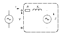
Figure 10.3 Equivalent circuit for synchronous machine
The similarity between this circuit and that of the d.c. machine (see Figure 3.6) and the induction motor (see Figure 5.8) is clear, and it stems from the fact that these machines produce torque by the interaction of a magnetic field and current-carrying conductors (the so-called ‘BIl’ effect). In the case of the d.c. machine the inductance was seen not to be important under steady-state conditions, because the current was steady (i.e. d.c.), and the resistance emerged as the dominant parameter. In the case of the mains-fed synchronous motor the current is alternating at mains frequency, so not surprisingly we find that the synchronous reactance is the dominant impedance and resistance plays only a minor role.
At this point readers who are not familiar with a.c. circuit theory can be reassured that they will not be seriously disadvantaged by skipping the rest of this and the following sections. But although no seminal truths are to follow, discussion of the equivalent circuit and the associated phasor diagram greatly assists the understanding of motor behaviour, especially its ability to operate over a range of power factors.
Our aim is to find the current drawn from the mains, which from Figure 10.3 clearly depends on all the parameters therein. But for a given machine operating from a constant-voltage, constant-frequency supply, the only variables are the load on the shaft and the d.c. current (the excitation) fed into the rotor, so we will look at the influence of both, beginning with the effect of the load on the shaft.
The speed is constant and therefore the mechanical output power (torque times speed) is proportional to the torque being produced, which in the steady state is equal and opposite to the load torque. Hence if we neglect the losses in the motor, the electrical input power is also determined by the load on the shaft. The input power per phase is
given by VI cos f, where I is the current and the power-factor angle is f. But V is fixed, so the in-phase (or real) component of input current (I cos f) is determined by the mechanical load on the shaft. We recall
that, in the same way, the current in the d.c. motor (see Figure 3.6) was determined by the load. This discussion reminds us that although the equivalent circuits in Figures 10.3 and 3.6 are very informative, they should perhaps carry a ‘health warning’ to the effect that the single most important determinant of the current (the load torque) does not actually appear explicitly on the diagrams.
Turning now to the influence of the d.c. excitation current, at a given supply frequency (i.e. speed) the mains-frequency e.m.f., (E) induced in the stator is proportional to the d.c. field current fed into the rotor. (If we want to measure this e.m.f. we could disconnect the stator windings from the supply, drive the rotor at synchronous speed by an external means, and measure the voltage at the stator terminals, performing the so-called ‘open-circuit’ test. If we were to vary the speed at which we drove the rotor, keeping the field current constant, we would of course find that E was proportional to the speed.) We discovered a very similar state of affairs when we studied the d.c. machine (see topic 3): its induced (‘back’) e.m.f. (E) turned out to be proportional to the field current, and to the speed of rotation of the armature. The main difference between the d.c. machine and the synchronous machine is that in the d.c. machine the field is stationary and the armature rotates, whereas in the synchronous machine the field system rotates while the stator windings are at rest: in other words, one could describe the synchronous machine, loosely, as an ‘inside-out’ d.c. machine.
We also saw in topic 3 that when the unloaded d.c. machine was connected to a constant voltage d.c. supply, it ran at a speed such that the induced e.m.f. was (almost) equal to the supply voltage, so that the no-load current was almost zero. When a load was applied to the shaft, the speed fell, thereby reducing E and increasing the current drawn from the supply until the motoring torque produced was equal to the load torque. Conversely if we applied a driving torque to the shaft of the machine, the speed rose, E became greater than V, current lowed out to the supply and the machine acted as a generator. These findings are based on the assumption that the field current remains constant, so that changes in E are a reflection of changes in speed. Our overall conclusion was the simple statement that if E is less than V, the d.c. machine acts as a motor, while if E is greater than V, it acts as a generator.
The situation with the synchronous motor is similar, but now the speed is constant and we can control E independently via the control of the d.c. excitation current fed to the rotor. We might again expect that if E was less than V the machine would draw in current and act as a motor, and vice versa if E was greater than V. But we are no longer dealing with simple d.c. circuits in which phrases such as ‘draw in
current’ have a clear meaning in terms of what it tells us about power low. In the synchronous motor equivalent circuit the voltages and currents are a.c., so we have to be more careful with our language and pay due respect to the phase of the current, as well as its magnitude. Things turn out to be rather different from what we found in the d.c. motor, but there are also similarities.
Phasor diagram and Power-factor control
To see how the magnitude of the e.m.f. influences behaviour we can examine the phasor diagrams of a synchronous machine operating as a motor, as shown in Figure 10.4. The irst point to clarify is that our sign convention is that motoring corresponds to positive input power to the
machine. The power is given by VI cos f, so when the machine is motoring (positive power) the angle f lies in the range ±90°. If the current lags or leads the voltage by more than 90° the machine will be generating.
Figure 10.4 shows three phasor diagrams corresponding to low, medium and high values of the induced e.m.f., (E), the shaft load (i.e. mechanical power) being constant. As discussed above, ifthe mechanical power is constant, so is I cos f, and the locus of the current is therefore shown by the horizontal dotted line. The load angle (d), discussed in Section 10.2.1, is the angle between V and E in the phasor diagram. In Figure 10.4, the voltage phasor diagram embodies Kirchhof’s law as applied to the equivalent circuit in Figure 10.3, i.e. V = E + IR + jIXs, but for the sake of simplicity R is neglected so the phasor diagram simply consists of the volt-drop IXs (which leads the current I by 90°) added to E to yield V.
10.4. The first point to clarify is that our sign convention is that motoring corresponds to positive input power to the
machine. The power is given by VI cos f, so when the machine is motoring (positive power) the angle f lies in the range ±90°. If the current lags or leads the voltage by more than 90° the machine will be generating.
Figure 10.4 shows three phasor diagrams corresponding to low, medium and high values of the induced e.m.f., (E), the shaft load (i.e. mechanical power) being constant. As discussed above, if the mechanical power is constant, so is I cos f, and the locus of the current is therefore shown by the horizontal dotted line. The load angle (d), discussed in Section 10.2.1, is the angle between V and E in the phasor diagram. In Figure 10.4, the voltage phasor diagram embodies Kirchhof’s law as applied to the equivalent circuit in Figure 10.3, i.e. V = E + IR + jIXs, but for the sake of simplicity R is neglected so the phasor diagram simply consists of the volt-drop IXs (which leads the current I by 90°) added to E to yield V.
Figure 10.4(a) represents a condition where the field current has been set so that the magnitude of the induced e.m.f., (E) is less than V. This is called an ‘underexcited’ condition, and as can be seen the current is lagging the terminal voltage and the power-factor is cos fa lagging. When the field current is increased (increasing the magnitude of E) the magnitude of the input current reduces and it moves more into phase with V: the special case shown in Figure 10.4(b) shows that the motor can be operated at unity power-factor if the field current is suitably chosen. Finally, in Figure 10.4(c), the field current is considerably higher (the ‘overexcited’ case) which causes the current to increase again but this time the current leads the voltage and the power-factor is cos fc leading. We see that we can obtain any desired power-factor by appropriate choice of rotor excitation, and in particular we can operate with a leading power-factor. This is a freedom not afforded to users of
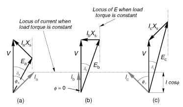
Figure 10.4 Phasor diagrams for synchronous motor operating with constant load torque, for three different values of the rotor (excitation) current
induction motors, and arises because in the synchronous machine there is an additional mechanism for providing excitation, as we will now see.
When we studied the induction motor we discovered that the magnitude and frequency of the supply voltage V governed the magnitude of the resultant flux density wave in the machine, and that the current drawn by the motor could be considered to consist of two components. The real (in-phase) component represented the real power being converted from electrical to mechanical form, so this component varied with the load. On the other hand the lagging reactive (quadrature) component represented the ‘magnetising’ current that was responsible for producing the flux, and it remained constant regardless of load.
The stator winding of the synchronous motor is the same as the induction motor, so it is to be expected that the resultant lux will be determined by the magnitude and frequency of the applied voltage. This flux will therefore remain constant regardless of the load, and there will be an associated requirement for magnetising MMF. But now we have two possible means of providing the excitation MMF, namely the d.c. current fed into the rotor and the lagging component of a.c. current in the stator.
When the rotor is underexcited, i.e. the induced e.m.f. E is less than V (Figure 10.4(a)), the stator current has a lagging component to make up for the shortfall in excitation needed to yield the resultant field that must be present as determined by the terminal voltage, V. With more field current (Figure 10.4(b)), however, the rotor excitation alone is sufficient and no lagging current is drawn by the stator. And in the overexcited case (Figure 10.4(c)), there is so much rotor excitation that
there is effectively some reactive power to spare and the leading power-factor represents the export of lagging reactive power that could be used to provide excitation for induction motors elsewhere on the same system.
To conclude our look at the synchronous motor we can now quantify the qualitative picture of torque production introduced in Section 10.2.1 by noting from the phasor diagrams that if the mechanical power (i.e. load torque) is constant, the variation of the load-angle (d) with E is such that E sin d remains constant. As the rotor excitation is reduced, and E becomes smaller, the load angle increases until it eventually reaches its maximum of 90°, at which point the rotor will lose synchronism and stall. This means that there will always be a lower limit to the excitation required for the machine to be able to transmit the specified torque. This is just what our simple mental picture of torque being developed between two magnetic fields, one of which becomes very weak, would lead us to expect.
Starting
It should be clear from the discussion of how torque is produced that unless the rotor is running at the same speed as the rotating field, no steady torque can be produced. If the rotor is running at a different speed, the two fields will be sliding past each other, giving rise to a pulsating torque with an average value of zero. Hence a basic synchronous machine is not self-starting, and some alternative method of producing a run-up torque is required.
Most synchronous motors are therefore equipped with some form of rotor cage, similar to that of an induction motor, in addition to the main field winding. When the motor is switched onto the mains supply, it operates as an induction motor during the run-up phase, until the speed is just below synchronous. The excitation is then switched on so that the rotor is able to make the final acceleration and ‘pull-in’ to synchronism with the rotating field. Because the cage is only required during starting, it can be short time rated, and therefore comparatively small. Once the rotor is synchronised, and the load is steady, no currents are induced in the cage, because the slip is zero. The cage does, however, come into play when the load changes, when it provides an effective method for damping out the oscillations of the rotor as it settles at its new steady-state load angle.
Large motors will tend to draw a very heavy current during run-up, so some form of reduced voltage starter is often required (see topic 6). Sometimes, a separate small induction motor is used simply to run-up
the main motor before synchronisation, but this is only feasible where the load is not applied until after the main motor has been synchronised.
No special starter is required for the wound-rotor induction motor of course, which runs up in the usual way (see topic 6) before the d.c. excitation is applied. Motors operated like this are sometimes known as ‘Inductosyns’.
Permanent magnet synchronous motors
Permanent magnets are used on the rotor instead of a wound field: typical 2-pole and 4-pole surface-mounted versions are shown in Figure 10.5, the direction in which the magnets have been magnetised being represented by the arrows. Motors of this sort have outputs ranging from about
100 W up to perhaps 100 kW.
For starting from a fixed-frequency supply a rotor cage is required, as discussed above. The advantages of the permanent magnet type are that no supply is needed for the rotor and the rotor construction can be robust and reliable. The disadvantage is that the excitation is fixed, so the designer must either choose the shape and disposition of the magnets to match the requirements of one specific load, or seek a general-purpose compromise. Control of power-factor via excitation is no longer possible.
Early permanent magnet motors suffered from the tendency for the magnets to be demagnetised by the high stator currents during starting, and from a restricted maximum allowable temperature. Much improved versions using high coercivity rare-earth magnets were developed during the 1970s to overcome these problems. They are usually referred to as ‘Line-Start’ motors, to indicate that they are designed for direct-on-line
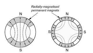
Figure 10.5 Permanent magnet synchronous motor rotors. 2-pole (left); 2-pole (right)
starting. The steady-state efficiency and power-factor at full load are in most cases better than the equivalent induction motor, and they can pull-in to synchronism with inertia loads of many times rotor inertia.
Hysteresis motors
Whereas most motors can be readily identified by inspection when they are dismantled, the hysteresis motor is likely to baffle anyone who has not come across it before. The rotor consists simply of a thin-walled cylinder of what looks like steel, while the stator has a conventional single-phase or 3-phase winding. Evidence of very weak magnetism may just be detectable on the rotor, but there is no hint of any hidden magnets as such, and certainly no sign of a cage. Yet the motor runs up to speed very sweetly and settles at exactly synchronous speed with no sign of a sudden transition from induction to synchronous operation.
These motors (the operation of which is quite complex) rely mainly on the special properties of the rotor sleeve, which is made from a hard steel which exhibits pronounced magnetic hysteresis. Normally in machines we aim to minimise hysteresis in the magnetic materials, but in these motors the effect (which arises from the fact that the magnetic flux density B depends on the previous ‘history’ of the MMF) is deliberately accentuated to produce torque. There is actually also some induction motor action during the run-up phase, and the net result is that the torque remains roughly constant at all speeds.
Small hysteresis motors are used extensively in tape recorders, office equipment, fans, etc. The near constant torque during run-up and the very modest starting current (of perhaps 1.5 times rated current) means that they are also suited to high inertia loads such as gyrocompasses and small centrifuges.
Reluctance motors
The reluctance motor is arguably the simplest synchronous motor of all, the rotor consisting simply of a set of laminations shaped so that it tends to align itself with the field produced by the stator. This reluctance torque’ action was discussed when we looked at the variable reluctance stepping motor (in topic 9) and again briefly in Section 10.2.
Here we are concerned with mains-frequency reluctance motors, which differ from steppers in that they only have saliency on the rotor, the stator being identical with that of a 3-phase induction motor. In fact, since induction motor action is required in order to get the rotor up to synchronous speed, a reluctance-type rotor resembles a cage induction
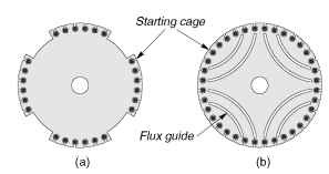
Figure 10.6 Reluctance motor rotors (4-pole): (a) salient type, (b) flux-guided type
motor, with parts of the periphery cut away in order to force the flux from the stator to enter the rotor in the remaining regions where the air-gap is small, as shown in Figure 10.6(a). Alternatively, the ‘preferred flux paths’ can be imposed by removing iron inside the rotor so that the flux is guided along the desired path, as shown in Figure 10.6(b).
The rotor will tend to align itself with the field, and hence is able to remain synchronised with the travelling ield set up by the 3-phase winding on the stator in much the same way as a permanent magnet rotor. Early reluctance motors were invariably one or two frame sizes bigger than an induction motor for a given power and speed, and had low power-factor and poor pull-in performance. As a result they fell from favour except for some special applications such as textile machinery where cheap constant speed motors were required. Understanding of reluctance motors is now much more advanced, and they can compete on almost equal terms with the induction motor as regards power-output, power-factor and efficiency. They are nevertheless relative expensive because they are not produced in large numbers.
