INTRODUCTION
In this topic we look at examples of the power converter circuits which are used with motor drives, providing either d.c. or a.c. outputs, and working from either a d.c. (battery) supply, or from the conventional a.c. mains. The treatment is not intended to be exhaustive, but should serve to highlight the most important aspects which are common to all types of drive converters.
Although there are many different types of converters, all except very low-power ones are based on some form of electronic switching. The need to adopt a switching strategy is emphasised in the first example, where the consequences are explored in some depth. We will see that switching is essential in order to achieve high-efficiency power conversion, but that the resulting waveforms are inevitably less than ideal from the point of view of the motor.
The examples have been chosen to illustrate typical practice, so for each converter the most commonly used switching devices (e.g. thyris-tor, transistor) are shown. In many cases, several different switching devices may be suitable (see later), so we should not identify a particular circuit as being the exclusive preserve of a particular device.
Before discussing particular circuits, it will be useful to take an overall look at a typical drive system, so that the role of the converter can be seen in its proper context.
General arrangement of drives
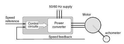
A complete drive system is shown in block diagram form in Figure 2.1. The job of the converter is to draw electrical energy from the mains (at
motor at whatever voltage and frequency necessary to achieve the desired mechanical output.
Except in the simplest converter (such as a simple diode rectifier), there are usually two distinct parts to the converter. The first is the power stage, through which the energy lows to the motor, and the second is the control section, which regulates the power low. Control signals, in the form of low-power analogue or digital voltages, tell the converter what it is supposed to be doing, while other low-power feedback signals are used to measure what is actually happening. By comparing the demand and feedback signals, and adjusting the output accordingly, the target output is maintained. The simple arrangement shown in Figure 2.1 has only one input representing the desired speed, and one feedback signal indicating actual speed, but most drives will have extra feedback signals as we will see later. Almost all drives employ closed-loop (feedback) control, so readers who are unfamiliar with the basic principles might find it helpful to read the Appendix at this stage.
A characteristic of power electronic converters which is shared with most electrical systems is that they have very little capacity for storing energy. This means that any sudden change in the power supplied by the converter to the motor must be reflected in a sudden increase in the power drawn from the supply. In most cases this is not a serious problem, but it does have two drawbacks. Firstly, a sudden increase in the current drawn from the supply will cause a momentary drop in the supply voltage, because of the effect of the supply impedance. These voltage ‘spikes’ will appear as unwelcome distortion to other users on the same supply. And secondly, there may be an enforced delay before the supply can furnish extra power. With a single-phase mains supply, for example, there can be no sudden increase in the power supply from the mains at the instant where the mains voltage is zero, because in-

Figure 2.1 General arrangement of speed-controlled drive stantaneous power is necessarily zero at this point in the cycle because the voltage is itself zero.
It would be better if a significant amount of energy could be stored within the converter itself: short-term energy demands could then be met instantly, thereby reducing rapid fluctuations in the power drawn from the mains. But unfortunately this is just not economic: most converters do have a small store of energy in their smoothing inductors and capacitors, but the amount is not sufficient to buffer the supply sufficiently to shield it from anything more than very short-term fluctuations.
