2.39.
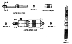
For the measurement of larger internal dimensions, inside micrometer is employed. It
consists of four parts: (i) Measuring head (micrometer unit), (ii) Extension rods, (iii) Spacing collars,
(iv) Handle (Refer Fig. 2.124.) Using one range of extension rods, distance between the contacting
surface is varied by rotating the thimble upto the extent of the screw length. Greater distances are
obtainable by the use of different extension rods and spacing collars. The measuring tip on the
thimble is adjustable one in order to compensate for the wear taking place. Spacing collars are used
when those dimensions are needed which cant’s be obtained by the use of extension rod and
micrometer unit. For using this instrument first the diameter of bore is measured approximately
by a scale. Extension rod is then chosen to the nearest one cm and inserted in the micrometer head.
Then zero error is checked by taking the dimension on standard sizes specimen. The micrometer is
then adjusted at a dimension slightly smaller than the diameter of bore. One micrometer head is
then held firmly against the bore and other contact surface is adjusted by moving the thimble till
correct feel is sensed. One contact surface must always be moved sideways up and down in order
to ensure that diameter is being measured and not chord. The micrometer is then removed and
reading taken. Dimension from the micrometer head is noted down and to this, lengths of extension
rod and collar are added up.
By suitable base arrangement, inside micrometer can be converted into height gauge.
It is used for measuring the inside diameters of cylinders, rings etc. and also for measuring
parallel surfaces and for setting calipers etc.
The desired range is obtained by assembling measuring rods and lapped gauges or spacing
collars to the micrometer held.

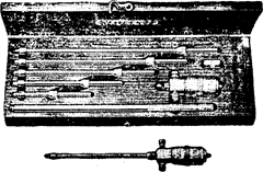
Fig. 2.123. Inside Micrometery (Commercially available inside micrometer set).
This form of internal micrometer is, in effect, merely an adjustable end measuring bar. As
in the case of an ordinary external micrometer, there is a barrel and a thimble, but no frame and
no spindle. The measuring points are at extreme ends and adjustment is effected by advancing or
withdrawing the thimble along the barrel. A series of anvil bars (extension rods) of different lengths
are provided in order to obtain a wide measuring range. When measurements are to be taken inside
the bores of comparatively small diameters, a handle of sufficient length is provided which can be
screwed into a radial hole in the barrel.
The description of various units of internal micrometer is given below :
Micrometer Unit. The body of the measuring head is made of suitable quality steel and its
spindle and terminal measuring faces are made of high grade tool steel. The measuring face of the
anvil is so designed as to have a hardness of about 800 HV (63.5 HRC). It is desirable that the
measuring face be tipped with tungsten carbide or other suitable hard material or be faced with a
deposit of hard chromium. The radius of curvature of the measuring face is made slightly less than
one-half of the smallest measuring range of the micrometer. The micrometer screw has a pitch of
0.5 mm and the threads of the screw and nut are truncated so as to continue contact to the flanks

Nomenclature of Internal Micrometer
Fig. 2.124
of the thread. The screw should travel smoothly throughout the length of its travel. An adjusting
nut is provided to arrange for the thimble to be sufficiently tight for the micrometer to retain its
reading after being set. There should be no perceptible backlash between the spindle screw and
nut. When the micrometer is at its’maximum reading, there should be full engagement of the nut
and micrometer screw. It is desirable that the travel of the micrometer be continued for at least one
turn of the screw beyond each end of the graduated scale on the barrel. Generally means are also
provided for compensation of wear between the screw and nut. The diameter of the graduated edge
of the thimble is generally not less than 10 mm. For ease of reading, the surfaces of the thimble
and barrel should have a dull finish and the graduation lines blackened.
Generally the micrometer is provided with means for adjusting the zero setting. The means
of adjustment should be such that after resetting, the parts are secured, and the original accuracy
of the instrument is not impaired. Suitable spanners and keys are provided for this adjustment.
The measuring head with its associated extension rods and collars should conform to the
following limits of error when tested at standard reference temperature of 20°C.
| Measuring range | Maximum permissible error in length |
| mm | mm |
| 25—150 | ± 0.005 |
| 150—300 | ± 0.010 |
| 300—450 | ± 0.015 |
| 450—600 | ± 0.020 |
The error in traverse of the micrometer screw should not exceed 0.003 mm, whether errors
are progressive or periodic in character.
Extension rods. These are provided in order to enable any measurement to be made
throughout the range specified for the set, spacing collars being used whenever necessary. These
are made of suitable material hardened upto 800 HV and the measuring faces are tipped with
tungsten carbide or other hard material. The measuring faces and the contact face are finished by
lapping operation. The extension rods may either incorporate their own measuring anvils or these
may take the form of different pieces to which a separate common anvil piece may be fitted. When
the extension rods have their own measuring faces, a suitable adjustment for zero setting is
incorporated in it (.e.g., the attachment of the anvil by means of a friction-tight fine pitch thread)
and there is no need of providing any such adjustment on the micrometer head. If the extension
rods have separate anvil pieces for measuring faces then the adjustment for zero setting may be
incorporated either in the anvil pieces or in the measuring head. The range of measurement for
which an extension rod is applicable is always marked on it.
Spacing collars. These are intended for smaller adjustments in the range of measurement.
The ends of the spacing collars are well finished by lapping and are flat and mutually parallel and
square to the axis. No sharp edges are there and at least one face of the spacing collar is provided
with dirt clearance grooves.
Handle. The micrometer set for the measuring range 25 to 50 mm is generally supplied with
a suitable detachable handle so that micrometer head can be easily lowered into deep holes.
The micrometer assembly with any combination of extension rods and spacing collars should
be very rigid. When the assembled unit is supported at its ends, then the deflection of mid-point
under an applied load of 0.5 kg should not exceed 0.05 mm for an assembly 150 mm long with an
increase of 0.05 mm for each increase in the length of 25 mm. The maximum deflection allowed for
an assembly 1 m long is 1.75 mm.
2.39.1.
Self-Centering Inside Micrometer.
Measures through bores, blind bores,
registers.
Consists of micrometer screw and screw-in, interchangeable measuring head.

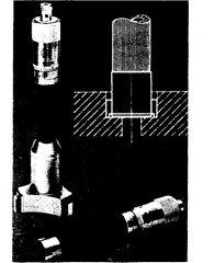
Fig. 2.125. Self-centering inside micrometer.
Components:
Micrometer Screw. Measuring spindle precision ground, hardened throughout. Ratchet
stop. Heat insulator. Moving parts and scales satin chrome finished. Threaded for convenient
mounting of measuring heads.
Measuring Head. Interchangeable. Three laterally protruding fingers, positioned at a 120°
angle to each other, provide self-centering action and firm positioning. Positively no tilting or
tipping. From 10 mm and up the fingers extend over the face of the head to allow measurements
through the entire bore length. Individual measuring heads.
