ABSTRACT
Accurate mechanical property measurement of films on substrates by instrumented indentation requires a solution describing the effective modulus of the film/substrate system. Here, a first-order elastic perturbation solution for spherical indentation on a film/substrate is presented. Finite element method (FEM) simulations were conducted for comparison with the analytical solution. FEM results indicate that the new solution is valid for a practical range of modulus mismatch, especially for a stiff film on a compliant substrate. It also shows that effective modulus curves for the spherical punch deviates from those of the flat punch when the thickness is comparable to contact size. The work is applicable in tribological films and other engineering systems requiring hard, protective coatings.
Introduction
Measurement of mechanical properties of films deposited on substrates has long been an issue in thin- and thick-film technology. Although indentation is extensively used due to its relative experimental simplicity, analysis is complicated by the inevitable substrate effect. Rules of practice exist that state film properties may be isolated if contact dimensions are small compared to film thickness, but such simplifications are not useful for layers including microstructural size effects (e.g., where contact dimensions are smaller than dislocation spacing, or splat size for thermal sprayed coatings), or ultra-thin films. Thus, analyses that consider the relation between film and substrate properties are necessary.
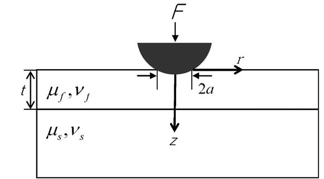
Figure 1. Schematic of spherical indentation on film/substrate system
Consider the indentation of an ideally elastic film/substrate system that is mechanically bonded (Figure 1). A proper description of the effective modulus ^ of the film/substrate system, in the context of film and substrate moduli (^ and jus) is essential to the accurate extraction of the film properties. Since there is no exact solution yet for this problem, a number of approximate models have been proposed to be fitted with data from experiments, and FEM simulations, or analytic solutions for several tip geometries. Those models have shown good yet limited applicability. Most of these approaches were based on the following simple formula:
where a is contact radius, t is the thickness of the film and $ is a weight function of contact size, tip geometry and modulus mismatch; $ approaches 1 when![]() Numerous forms of Eq (1) have been proposed for sharp and flat-ended cylindrical geometry:
Numerous forms of Eq (1) have been proposed for sharp and flat-ended cylindrical geometry:
• Doerner and Nix[1] first introduced an empirical equation of an effective modulus expressed as an exponential form and fit it with experimental data obtained with a sharp tip.
• King[2] performed a numerical analysis of flat-ended tip indentation and introduced a similar equation to Doerner and Nix’s.
• Jung et al.[3] developed a power law function based on their experimental results from nanoindentation with ceramic films on silicon substrates. The above empirical equations have adjustable parameters which must be determined by experiment, or numerically.
• Gao, et al.[4] performed a first order perturbation analysis on the flat-ended cylindrical punch problem, and presented a formula for effective modulus ^ .
• Mencik, et al. [5] compared this and several empirical equations with experimental data from nanoindentation, and found that Gao et al. ‘s equation gave the best fit to their experimental data.
• Xu and Pharr[6] later modified the perturbation solution and comparison with FEM results showed better accuracy for a wide range of modulus mismatch.
The perturbation solution is attractive because it is given as a closed form and doesn’t include adjustable parameters. But its assumption on flat-ended cylindrical geometry limits the applicability for sharp or spherical tip indentation, particularly when a and t are comparable. Different tip geometries have been considered in other investigations:
• Perriot and Barthel[7] used numerical integration to get effective modulus curves for sharp and spherical tips, and showed they overlap closely, but differ from those for a flat-ended cylindrical tip.
• Clifford and Seah[8] conducted FEM simulations with spherical tip geometry to get effective modulus curves for compliant polymer films on stiff substrates and proposed a curve-fit equation.
• Finally, Hsueh and Miranda[9] presented an approximate, analytically derived equation of effective modulus under spherical tip indentation, based on an extension of the Boussinesq Green’s function. Using FEM simulations, they showed that their results were valid for a certain range of modulus mismatch, but most accurate for the case of a compliant film on a stiff substrate.
There is an opportunity to revisit the problem of spherical indentation of a bilayer, with particular attention to the stiff film on compliant substrate. From the above investigations it appears that inaccuracies may arise when tip geometry is assumed inappropriately (e.g., flat punch assumption for spherical punch indentation experiment). To investigate this, here we use the first-order perturbation solution, and modify it for a spherical tip geometry.
Perturbation analysis
The full description of the perturbation analysis can be found in [10], here the approach is briefly described. In perturbation analysis, the film/substrate system is treated as a homogeneous material with (initially) properties of the substrate that undergoes a phase transformation to assume film properties in the region 0 < z < t. During the transformation, the load F is fixed and the displacement h is allowed to change to![]() . The force-displacement relation for spherical indentation of an elastic material, is described by Hertzian relation[11] as
. The force-displacement relation for spherical indentation of an elastic material, is described by Hertzian relation[11] as
Eq. 2 contains a single value for shear modulus and Poisson’s ratio, but a composite value is used to represent the film/substrate system [8, 9, 12]. Upon the phase transformation, the extra work done by the force F due to the displacement change Sh is thus calculated as [13]
The additional work is equal to the strain energy change due to moduli variation in the body, and the energy conservation equation can be written as
where![]() is the change of moduli from substrate material to film material and u° is the known displacement field for the homogeneous substrate material. The right term of Eq. 4 is the energy variation due to a moduli transformation, and can be rearranged (following Gao, et al.) as homogeneous substrate material. The right term of Eq. 4 is the energy variation due to a moduli transformation, and can be rearranged (following Gao, et al.) as
is the change of moduli from substrate material to film material and u° is the known displacement field for the homogeneous substrate material. The right term of Eq. 4 is the energy variation due to a moduli transformation, and can be rearranged (following Gao, et al.) as homogeneous substrate material. The right term of Eq. 4 is the energy variation due to a moduli transformation, and can be rearranged (following Gao, et al.) as
where
![]() is the Lame constant of the substrate,
is the Lame constant of the substrate,
and and so are the known stress and strain field for the homogeneous substrate material[4]. The terms Vj and Af in Eq. 5 indicate the domain volume and the surrounding surface domain of the film region, respectively. The surface domain consists of two planes: z = 0 and z = t. The surface stress and displacement solutions for spherical indentation of an elastic homogeneous material are known[11], and substituting into Eq. 5 leads to the following expression for 8h /h
The original displacement h is calculated from the Hertz relation[10] such as
Since the total displacement ht is given as
where
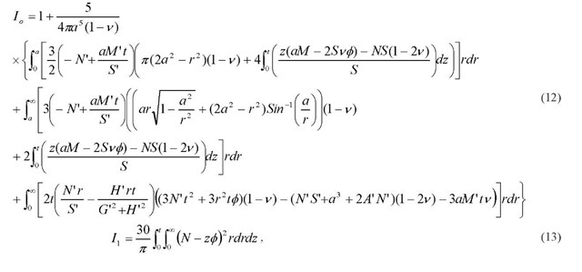
Eq. 9 is thus the perturbation equation for spherical indentation. The terms Io and Ij are weighting functions representing modulus difference and Poisson’s ratio difference, respectively. Here, the elastic solutions for the spherical punch problem given by Hamilton [14, 15] are used to obtain new Io and Ij for spherical indentation:
where A, S’, M’, N’, G’, H’ are variables at z = t found in [14,15]. Equations (12) and (13) can be substituted into the following equation [6]:
Giving the normalized displacement after rearrangement as:
This term, denoted as h. / h, compares tip displacement under identical loading conditions, between a composite material J and a homogeneous material having film properties. 3. Results and Discussion
Figure 2 illustrates the normalized displacement (Eq. 15) curves comparing the current work with FEM results and Hsueh’s model[9]. Note that Hsueh’s model gives a very similar result to the current solution when the modulus mismatch is small for the case of stiff films, but when the mismatch increases, it shows larger deviation. For jf / j = 10, both Hsueh’s and the current solution deviate from the FEM results when a /1 . Hsueh et. al attributed this discrepancy to flexural stresses in the film. The current solution underestimates the modulus in the case of compliant films. We find this acceptable, as Hsueh’s solution is sufficiently accurate in those cases. In the case of stiff films, the current solution appears most accurate when a and t are comparable. Recently, work by Zhou and Prorok[16] has demonstrated that taking into consideration the discontinuity in strain at the film-substrate interface provides a better match with experimental data over the Gao and Doerner and Nix models.
Figure 2. Normalized displacement, ht / h, curves for the current work with comparison to FEM results and Hsueh’s model: ![]()
Conclusions
In this paper, we presented a new analytic solution for spherical indentation of a linear elastic film/substrate bilayer based on the perturbation approach previously used by Gao et al[4]. The new weighting functions (Io, ) have similar shapes to those for flat punch, but deviate over most of the contact dimension range. We used the equation suggested by Gao et al.[4] and the one modified by Xu and Pharr[6] to combine weighting functions and give effective modulus curves. The new perturbation solution gives good agreement with FEM results for stiff layers on substrates, relevant for a number of engineering systems.


