During forensic analysis of the weaker specimens, we discovered that the polyurea felt sticky and failure occurred in the polyurea itself as opposed to within the wood fibers. We attributed this problem to incomplete mixing which most likely occurred when one of the canisters in the spray gun ran dry before the other. The interesting thing is that although the peak load is very different for the weak and strong specimens, for a given polyurea, the shapes of the curves are similar.
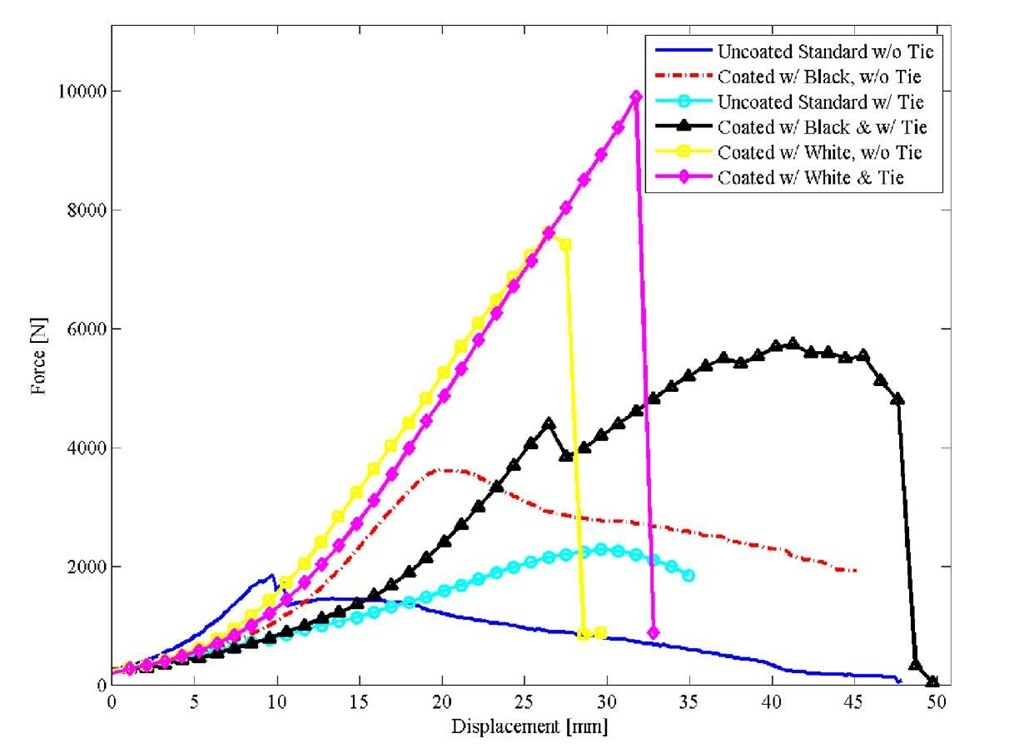
Figure 14 includes load/deflection plots corresponding to pull out for all six cases tested: 1) an unreinforced configuration, 2) a configuration reinforced with a hurricane tie, 3) an unreinforced configuration coated with black polyurea, 4) an unreinforced configuration coated with white polyurea, 5) a reinforced configuration coated with black polyurea, and 6) a reinforced configuration coated with white polyurea.
Fig. 14 Load versus deflection plots for 2 by 4 end nail failure in six different configurations
Table 1 lists the maximum loads that these six different configurations took along with the value of total deflection at which they occurred and the total strain energy required to achieve the maximum load condition. The net deflection and strain energy for each configuration was obtained by subtracting the values associated with the pull straps (see Equations 1 and 2).
Table 1 Tabulated results for 2 by 4 end nail failure in six different configurations
|
Configuration Status |
Maximum Load (Pmax) (N) |
Total Deflection @ Pmax (mm) |
Deflection @ Pmax (mm) |
Total Strain Energy to Pmax (N mm) |
Strain Energy to Pmax (N mm) |
|
uncoated standard w/o tie |
1850 |
9.7 |
8.1 |
8699 |
7231 |
|
uncoated standard w/tie |
2277 |
29.7 |
27.7 |
35814 |
33668 |
|
coated w/black w/o tie |
3621 |
19.8 |
16.8 |
28810 |
23274 |
|
coated w/white w/o tie |
7624 |
26.4 |
20.1 |
81571 |
57167 |
|
coated w/black & tie |
5738 |
41.4 |
36.6 |
113544 |
99648 |
|
coated w/white & tie |
9901 |
31.8 |
23.4 |
121340 |
80102 |
Table 2 lists the multiplication factors associated with coated specimens computed by taking the value found for a given quantity and dividing it by the value determined for its standard counterpart. The net strain energy is equal to the work done as the load is slowly applied and represents the amount of energy required to bring each configuration to the maximum load condition.
Table 2 Multiplication factors; 2 by 4 end nail failure in coated configurations
|
Configuration Status |
Load (Pmax) wrt Standard |
Total Deflection @ Pmax wrt Standard |
Deflection @ Pmax wrt to Standard |
Total Strain Energy to Pmax wrt Standard |
Strain Energy to Pmax wrt Standard |
|
coated w/black w/o tie |
1.96 |
2.05 |
2.07 |
3.31 |
3.21 |
|
coated w/white w/o tie |
4.12 |
2.74 |
2.47 |
9.38 |
7.87 |
|
coated w/black & tie |
2.52 |
1.39 |
1.32 |
3.17 |
2.96 |
|
coated w/white & tie |
4.35 |
1.07 |
0.84 |
3.39 |
2.38 |
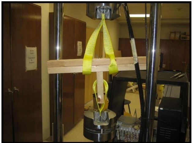
As mentioned previously, all specimens except for one failed as the nails in the top plate pulled out of the stud. As illustrated in the photo in Fig. 15, we subsequently tested the remaining joint on this configuration by placing pull straps over the top plate and through the hole in the stud. The partial configuration held 2998 N (674 lb) when it was reloaded.
Fig. 15 A partial configuration is retested for 2 by 4 end nail failure
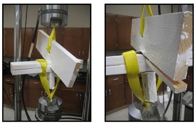
As illustrated in the photo shown to the left in Fig. 16, we tested the other partial configurations that did not include a hurricane tie by placing pull straps over the top plate and through the hole in the rafter. The photo shown to the right in the figure shows how the toe nail joint failed in the coated specimens as a crack developed and propagated along the rafter. This was notably different from the failure that occurred in the standard (described previously and shown in Fig 4) where the wood surrounding the nails fractured.
Figure 17 shows plots of load versus total deflection (of the configuration and the pull straps) corresponding to toe nail fracture for an uncoated standard (described previously and shown in Fig. 4) and configurations coated with black and white polyurea.
Fig. 16 When partial coated configurations were retested to evaluate toe-nail rafter failure (left) a crack developed in the rafter (right)
Fig. 17 Load versus deflection plots for toe-nail rafter failure of the uncoated unreinforced standard and unreinforced configurations coated with black and white polyurea
Table 3 lists the maximum loads that these three different configurations took along with the value of total deflection at which they occurred and the total strain energy required to achieve the maximum load condition. The net deflection and strain energy for each configuration was obtained by subtracting the values associated with the pull straps (see Equations 1 and 2).
Table 3 Tabulated results for toe-nail rafter failure in three different unreinforced configurations
|
Configuration Status |
Maximum Load (Pmax) (N) |
Total Deflection @ Pmax (mm) |
Deflection @ Pmax (mm) |
Total Strain Energy to Pmax (N mm) |
Strain Energy to Pmax (N mm) |
|
uncoated standard w/o tie |
2562 |
18.3 |
16.3 |
20788 |
18077 |
|
coated w/black w/o tie |
7949 |
55.1 |
48.5 |
155798 |
129248 |
|
coated w/white w/o tie |
10164 |
36.3 |
27.7 |
119306 |
75922 |
Table 4 lists the multiplication factors associated with coated specimens computed by taking the value found for a given quantity and dividing it by the value determined for its standard counterpart.
Table 4 Multiplication factors; toe-nail rafter failure in unreinforced coated configurations
|
Configuration Status |
Load (Pmax) wrt Standard |
Total Deflection @ Pmax wrt Standard |
Deflection @ Pmax wrt to Standard |
Total Strain Energy to Pmax wrt Standard |
Strain Energy to Pmax wrt Standard |
|
coated w/black w/o tie |
3.10 |
3.01 |
3.00 |
7.49 |
7.17 |
|
coated w/white w/o tie |
3.97 |
1.99 |
1.72 |
5.74 |
4.21 |
DISCUSSION
Referring to Tables 1 – 4, there are many factors that could have contributed to deviations and potential errors in the values determined for deflection and strain energy such as variations in wood grain and structure, kinks in the straps, elongation of the holes at the attachment points, variations in strap length, and differences in construction and the manner in which failure took place. But the results presented for peak load are indisputable.
It is clear from the tabulated data that the addition of a polyurea coating allowed both the unreinforced and reinforced configurations to withstand a greater load. Results for nail pull out indicate that when compared to their uncoated counterparts, the black coated configurations were about twice as strong whereas the white coated configurations were four times as strong. The follow up tests conducted to evaluate toe nail fracture show that when compared to their uncoated counterpart, the black coated configurations were three times as strong whereas the white coated configurations were four times as strong.
A review of the load/deflection plots revealed that the peaks corresponding to the maximum load in the unreinforced coated configurations always occurred at a greater deflection than those corresponding to their uncoated counterparts. Thus, the addition of a polyurea coating delayed the onset of failure allowing the unreinforced configurations to sustain more deflection before they reached their peak loads. Results for nail pull out and toe nail fracture indicate that when compared to their uncoated counterpart, the coated configurations can sustain anywhere from two to three times as much deflection.
The fact that it can take almost eight times more energy to bring a coated unreinforced configuration to the peak load as compared to that required to bring an uncoated unreinforced configuration to the same condition is staggering. Even when the configuration is reinforced, the strain energy associated with the coated configurations is more than double that associated with their uncoated counterparts. Significantly, the polyurea significantly strengthened both the unreinforced and reinforced configurations by increasing the amount of work/energy required to pull them apart.
Since nearly all hurricane straps are made of galvanized steel, there is limited design flexibility from a materials standpoint. This makes it difficult to design a configuration that can readily adapt in real time to withstand sustained winds or wind gusts. Referring again to the plots, the differences in the peaks and shapes associated with the coated configurations show that the failure mode of the unreinforced and reinforced configurations can be controlled by using different types of polyurea. The configuration can be designed to fail at a higher peak load in a relatively brittle fashion or at a lower load in a relatively ductile manner. If this knowledge can be harnessed and used to advantage, polyurea coatings may revolutionize how construction in hurricane prone regions is done.
The hurricane tie, as installed, only increased the peak load of the unreinforced configuration by about 25% and allowed the configuration to deflect three times as much before the maximum load was achieved. Significantly, we have shown that, when used in combination with a hurricane tie, a polyurea coating substantially enhanced the structural performance even when the strap alone does little to strengthen the uncoated joint.
In contrast to existing metal hurricane ties that are designed to withstand a specific loading, a polyurea coating provides more universal strengthening with the added advantage that members and joints can be protected from a multitude of threats such as corrosion due to moisture and damage due to flood and, with self extinguishing properties, fire.
CONCLUSIONS
In conclusion, we had a licensed carpenter construct several rafter top plate model joint connections. We performed tension tests on these configurations, some of which were reinforced with a hurricane tie, to establish how much of a difference a polyurea coating made as the joints between the stud and top plate, and top plate and rafter, were loaded to failure.
The addition of the coating allowed both unreinforced and reinforced configurations to withstand higher loads (200-400% more). In general, the polyurea delayed the onset of failure and significantly strengthened every configuration by increasing the amount of work/energy required to pull it apart; in some cases, by almost 800%. We showed that the failure mode can be controlled by using different types of polyurea and proved that the commercial applications of using polyurea to strengthen structures in hurricane prone areas are enormous. Polyurea provides universal strengthening compared to hurricane ties with the added advantage that members and joints can be protected from a multitude of threats including corrosion due to moisture, damage due to flood; and, with self extinguishing properties, fire.


