INTRODUCTION
Computer graphics is currently the spine of several industries of information technology. From computer aided design of almost all objects surrounding us, through virtualization of 3D environments such as Google Earth, to video games, 3D graphics becomes a valuable media with a similar impact as the one of video, image and audio. Such digital assets should be exchanged between producers, service providers, network providers and device manufacturers. Supporting large-scale interoperability needs the development and deployment of open standards. ISOa, as a major international standardization organization, anticipated this issue and proposed in the last decade several standards addressing 3D graphics assets exchange. VRML (ISO, 1997) (Virtual Reality Modeling Language), published in 1997, provides basic geometry primitives, appearance models and animation mechanisms for representing 3D objects and scenes. Built on top of VRML, the first version of MPEG-4 (ISO, 1998) supports tools for the compression and streaming of graphics assets. Since then, MPEG improved the 3D graphics compression technologies and published the MPEG-4 Part 16 (ISO, 2004) in order to address theses issues within a unified and generic framework.
This chapter is dedicated to professionals of 3D graphics industry, solution providers for on-line systems involving 3D content (games, persistent universes, virtual spaces with graphical representation), students and professors in digital sciences.
The first section aims at presenting the background of the compression for multimedia signals. The second section presents the latest developments in MPEG-4 with respect to the compression and streaming of 3D graphics objects and scenes. The MPEG-4 tools, categorized into geometry, appearance and animation, are introduced. While MPEG standards specify only the bit-stream syntax and the architecture of the decoder, scheme for encoders’ implementation are presented in this section.
In the third section we describe a recently adopted MPEG model for 3D graphics consisting in opening the representation of graphics primitives to any XML-based format and completing it with binarization and compression layers. This shift in the manner of using MPEG-4 for 3D graphics is concretized in Part 25 of MPEG-4 (Preda, Jovanova, Arsov& Preteux, 2007).
BACKGROUND
A generic compression schema aims at eliminating redundancy in the data representation. Additionally when dealing with lossy compression, it makes also possible to identify the attributes for which a less precise reconstruction results in an acceptable signal distortion for human observers. As example, image and video encoders exploits the way that humans perceive the colors. In general, a compression schema is based on prediction, frequency transform, quantization, and entropy encoder as illustrated in Figure 1.
Figure 1. Generic signal compression schema
Table 1. MPEG-4 tools for 3D graphics compression
| Compression Tool | Type |
| 3D Mesh Compression | Geometry |
| Wavelet Subdivision Surface | Geometry |
| Coordinate, Orientation and Position Interpolator | Animation |
| Bone-based Animation | Animation |
| Frame-based Animated Mesh Compression | Animation |
| Octree Compression for Depth Image-based Representation | Appearance |
| Point Texture | Appearance |
Compression is necessary when data should be transmitted over the networks or to optimize the data storage. Nowadays, it is used in many applications of the real life: photo cameras, digital television, DVDs, video servers on the Internet (like Youtube) and so forth. Forecasting the importance of the compression for the development of multimedia applications, the MPEG consortium initiated in 1998 an international standardization project for specifying bit-stream syntax for audio and visual information. The first product, called MPEG-1 was designed for compressing video and audio at low bit-rates. A world-wide recognized part of MPEG-1 is the MP3format, used for compressing music data. The second product, MPEG-2 was designed for compressing video and audio in high-quality. The technical performances of MPEG-2 explain the success of applications such as DVDb (used by the movie industry) and DVBc (used in television). MPEG-4 completes the compression solutions provided by the MPEG consortium and is the main focus of the current chapter.
MAIN FOCUS OF THE CHAPTER: MPEG-4 TOOLS FOR 3D GRAPHICS COMPRESSION
A major advancement of MPEG-4 over its predecessors, MPEG-1 and MPEG-2, is the extension of data types to rich media, offering the possibility to handle, in a unique format, pixel-based image representation, 2D scalable vector graphics and 3D graphics. On top of these representations, the MPEG consortium developed generic and data-specific compression tools. In order to handle the composition and presentation of various media elements in the scene as well as the user interactivity, MPEG-4 introduced the concept of scene graph by adopting the VRML specifications and adapting it to specific requirements of streaming. A first tool responding to such adaptation is BIFSd (ISO, 2005), a binary encoded version of an extended set of VRML. Designed as a generic tool, BIFS attempts to balance the compression performances with the extensibility, ease of parsing and simple bit-stream syntax. It includes the traditional modules such as prediction, quantization and entropy coding, without pushing them to extreme complexity. With respect to the textual description of the same data, BIFS may compress by a factor up to 15:1, depending on quantization step. However, for 3D graphics primitives and for animation, BIFS does not fully exploit the spatial and respectively, temporal correlation of (animated) 3D objects. To overcome this limitation, MPEG defined specific tools in Part 16 of the MPEG-4 standard.
For compressing 3D graphics assets, MPEG-4 offers a rich set of tools classified with respect to the data type, namely geometry, appearance and animation (Table 1).
The following sections describe the key elements for geometry and animation compression tools.
3D Mesh Compression (3DMC)
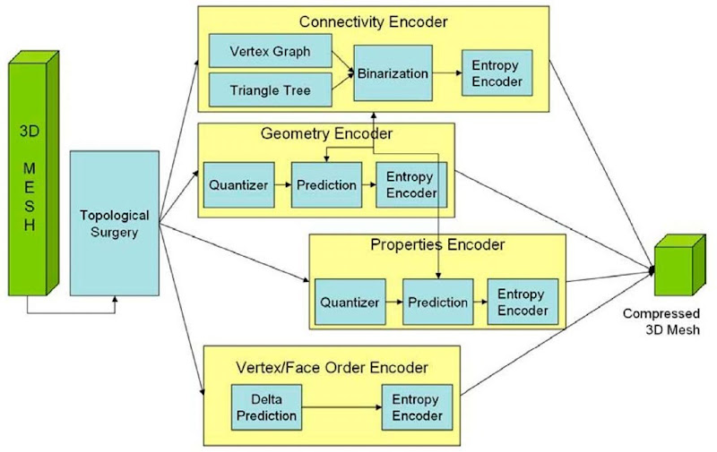
3DMC, initially published in 1999 (ISO, 1999) and extended in 2007 (ISO, 2007) is based on the Topological Surgery (TS) representation (Taubin & Rossignac, 1998). It applies to 3D meshes defined as an indexed list of polygons and consists of geometry, topology and properties (e.g., color, normal, texture coordinate, and other attributes).
The connectivity information is encoded loss-less, whereas the other information could be quantized before compression. In order to maintain the congruence of the system, geometry and properties information are encoded in a similar fashion. 3DMC supports three modes of compressing the mesh: single resolution, when the entire mesh is encoded as indivisible data, incremental representation, when data is interleaved such as each triangle may be rendered immediately after decoding, and the hierarchical mode, when an initial approximation of the mesh is improved by additional decoding of the details. 3DMC supports error resilience and computational graceful degradation. The extension published in 2006 allows preserving vertex and/or triangle order and improves compression of the texture mapping information. When using 3DMC or its extension, the compression gain is up to 40:1 with respect to textual representation. Figure 2 shows the encoder scheme highlighting the main components.
Figure 2. General block, diagram ofan MPEG-4 3Dmesh encoder
Wavelet Subdivision Surface Streams (WSS)
Wavelet methods for geometry encoding are a superset of multi-resolution analysis which has proven to be very efficient in terms of compression and adaptive transmission of three-dimensional (3D) data. The decorrelating power and space/scale localization of wavelets enable efficient compression of arbitrary meshes as well as progressive and local reconstruction. Especially for signal transmission purposes, subband decomposition is a very important concept. Not only does it permit to send a coarse version of the signal first and progressively refine it afterwards, but it also enables a more compact coding of the information carried by signals whose energy is mostly concentrated in their low-frequency part.
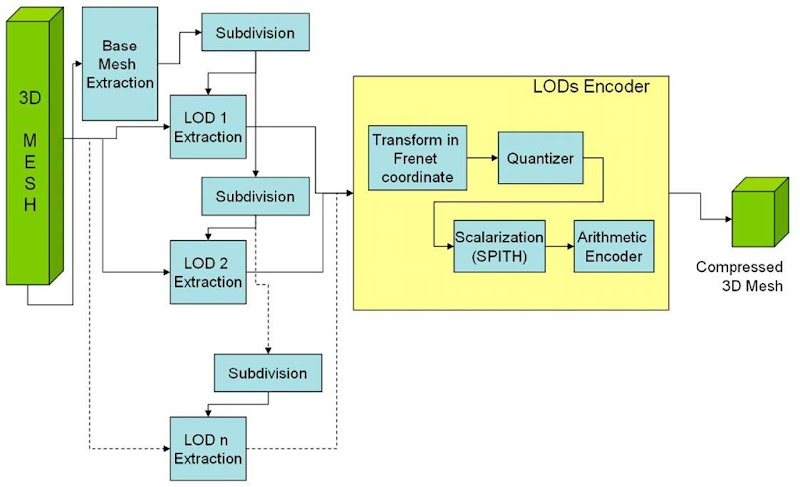
WSS of MPEG-4 is a hierarchical compression tool that uses a list of indexed triangles as a base mesh and encodes the vertex positions at different resolution levels based on subdivision surface predictors. The WSS contains only corrections of vertex position prediction encoded by using SPIHT (Set Partitioning In Hierarchical Trees) technique (Said & Pearlman, 1996); for all the other attributes defined per vertex (normals, colors, texture coordinates, etc.) linear interpolation schemes are used. WSS is well suited for applications such as terrain navigation. Optimal systems using WSS (Gioia,Aubault & Bouville, 2004) combines algorithms for local updates, cache management and server/client dialog and reports compression gain of up to 40:1. The schema of a WSS encoder is illustrated in Figure 3.
Coordinate Interpolator, Orientation Interpolator and Position Interpolator Streams (CI, OI and PI)
Interpolator representation in key-frame animation is currently the most popular method for computer animation. The interpolator data consist of key and key value pairs, where a key is a time stamp and a key value is the corresponding value to the key. Depending on the data type (coordinate, orientation, or position) the key value may have different dimension. The key value for coordinate and position is the set of X, Y and Z (dimension 3), while for the orientation it is represented as an axis and an angle (dimension 4).
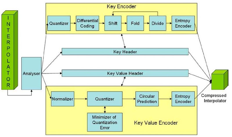
The structure of the Interpolator Compression (IC) is illustrated in Figure 4. First, the original interpolator data may be reduced through an analyzer with the role of removing the redundant or less meaningful keys from the original set. A redundant key is defined as a key that can obtained from its neighbors by interpolation and a less meaningful key is one for which the distortion between the original signal and the one reconstructed by interpolation is below a given threshold.
Figure 3. General block diagram of an MPEG-4 WSS Encoder.
Once the significant keys are selected, each component of a pair (key, key value) is processed by a dedicated encoder.
The key data, an array with monotonically non-decreasing values and usually unbounded, is first quantized and a delta prediction is applied. The result is further processed by a set of shift, fold, and divide operations with the goal of reducing the signal range (Jang, 2004).
Figure 4. Interpolators encoder
Data such as number of keys and quantization parameters are encoded by a header encoder using dictionaries. For the key values, the data is first normalized within a bounding box and then uniformly quantized. The quantized values are predicted from their one or two already transmitted key-values and the prediction errors are arithmetically encoded.
By using this method for representing interpolators, the compression performances are up to 30:1 with respect to textual representation of the same data.
Bone-Based Animation Stream (BBA)
In order to represent compactly the animation data (varying different vertex attributes, mainly spatial coordinates, but also normals or texture coordinates), some kind of redundancy in the animation is exploited: either temporal or spatial. In the first case, linear or higher order interpolation is used to compute the value of an attribute based on key values. In the second, vertices are clustered and a unique value or geometric transform is assigned to each cluster. For avatar animation, MPEG published BBA (Preda, Salomie, Preteux & Lafruit, 2004) which is a compression tool for geometric transforms of bones (used in skinning-based animation) and weights (used in morphing animation). These elements are defined in the scene graph and should be uniquely identified. The BBA stream refers to these identifiers and contains, at each frame, the new transforms of bones (expressed as Euler angles or quaternion) and the new weights of the morph targets.
A key point for ensuring a compact representation of the BBA animation parameters consists in decomposing the geometric transformations into elementary motions. For example, when using only the rotation component of the bone geometric transformation, a binary mask indicates that the other components are not involved. The compactness of the animation stream can still be improved when dealing with rotations by expressing them in local coordinates system. The rotation can be represented either as a quaternion (4 fields to be encoded) or as Euler angles (3 fields to be encoded).
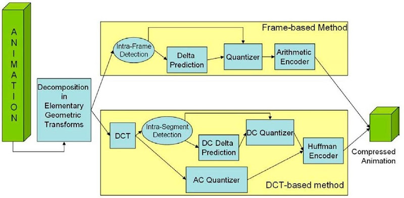
BBA follows traditional signal compression schema by including two encoding methods as illustrated in Figure 5. Optimized implementation (Preda et al., 2007) of the BBA encoder obtains up to 70:1 compression factor with respect to a textual representation.
Frame-Based Animated Mesh Compression Stream (FAMC)
FAMC is a tool to compress an animated mesh by encoding on a time basis the attributes (position, normals, etc.) of vertices composing a mesh. FAMC is independent on the manner how animation is obtained (deformation or rigid motion). The data in a FAMC stream is structured into segments of several frames that can be decoded individually. Within a segment, a temporal prediction model, used for motion compensation, is represented.
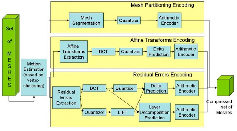
Each decoded animation frame updates the geometry and possibly the attributes of the 3D graphic object that FAMC is referred to. Once the mesh is segmented with respect to motion of each cluster, three kinds of data are obtained and encoded as illustrated in Figure 6. First, the mesh partitioning indicates for each vertex the attachment to one or several clusters. Secondly, for each cluster an affine transform is encoded by following a traditional approach (frequency transform, quantization, prediction of a subset of the spectral coefficients, and arithmetic encoder). Last, for each vertex a residual error is encoded. The frequency transform may be chosen between DCT and Wavelet (LIFT) and the prediction may be delta prediction or one based on multi-layer decomposition of the mesh. Current implementation (Mamou, 2007) of the FAMC encoders reports up to 45:1 compression factor with respect to a textual representation.
Figure 5. BBA Encoder.
Figure 6. FAMC encoder
FUTURE TRENDS: MPEG-4 PART25, A NEw MANNER TO ACCESS MPEG COMPRESSION
Initially, all the 3D graphics compression tools developed by MPEG were designed to be applied on top of graphics primitives specified by BIFS. Each compression tool corresponds to one or several nodes in the scene graph, being able to efficiently encode the information of the node (as in the case of geometry tools) or to update some fields of the node (as in the case of animation tools).
Recent developments in the space of 3D graphics formats show a large diversity for definition of scene graph and graphics primitives, several standards being available today. The most known are COLLADA by Khronos Groupe, X3D by Web3D Consortium and XMT by MPEG. Other proprietary formats are defined, in general each authoring tool having a proprietary format. Some of them include rich sets of primitives; others are specialized for specific data (e.g. avatars for H-Anim). The majority of them use XML (XML, 2006). However, beside MPEG-4, none of them provide tools for compression, in general an entropy encoder (usually gzip) satisfying this need.
The goal of P25 of the MPEG-4 standard, also called 3D Graphics Compression Model, is to specify an architectural model able to accommodate third-party XML based description of scene graph and graphics primitives with binarisation tools and with MPEG-4 3D Graphics compression tools.
The advantages of such approach are on one side the use of powerful MPEG-4 compression tools for graphics and, one another side, the support of a large set of graphics primitives formats. Hence the compression tools described in previous section would not be applied only to the scene graph defined by MPEG but to any scene graph definition. The bit-streams obtained when using the P25 model are MP4 formatted and contain XML (or binarized XML) data for scene graph and binary elementary streams for graphics primitives (geometry, texture and animation).
Architecture Model
The architectural model has three layers: Textual Data Representation, Binarisation and Compression. In the Textual Data Representation layer, the model can accommodate any scene graph and graphics primitives’ representation formalism. The only requirement on this representation is that it should be expressed in XML. Any XML Schema (specified by MPEG or by external bodies) may be used. Currently P25 supports the following XML Schemas: XMT, COLLADA, X3D, for each one the standard indicating the connection between the XML elements and the compression tool.
Figure 7. Encoding path in Part 25
The Binarisation layer provides a generic binarisation tool of the XML Schema. The XML data is represented in a “meta” atom of an MP4 file and can be textual or binary (gzip).
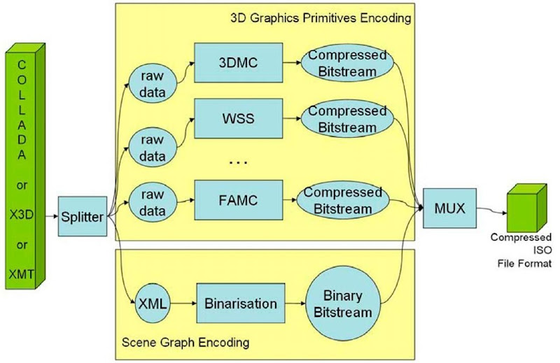
Finally, the compression layer includes the elementary streams listed in Table 1 and encoded as specified in the previous sections. A usual implementation of an MPEG-4 encoder generating bit-streams compliant with P25 is indicated in Figure 7. The MUX is used for multiplexing the elementary streams and formats the MP4 file.
CONCLUSION
This overview is purposed to the standardization of compression for different graphics primitives as specified in MPEG-4. This standard addresses a complete set of such primitives, ensuring efficient representation and streaming capabilities and allowing for reduction of the data size up to 70 times. Initially designed as a complete solution for 3D graphics (by specifying a formalism for textual representation usable for production purposes together with the compression tools), MPEG-4 recently opened the door to third-party solutions for graphics primitive formalisms, building a generic architectural model, called P25. The model is able to accommodate the MPEG compression tools on top of XML representation. Therefore, with P25, MPEG-4 for 3D graphics becomes a transparent layer for storage and transmission, without imposing a format for content production or/and consumption.
KEY TERMS
MPEG: “Motion Picture Expert Group”, marketing name of the “ISOIEC SC29 WG11″ standardization committee, affiliated to ISO (International Standardization Office) and creator of the multimedia standards: MPEG-1, MPEG-2, MPEG-4, MPEG-7 and MPEG-21.
3DGC: “3D Graphics Compression” – an MPEG working group dealing with specifications of 3D Graphics tools and integration of synthetic and natural media in hybrid scenes.
3DMC: “3D Mesh Compression” – a part of MPEG-4 specifications dealing with the specification of the bit-stream syntax for compressed meshes.
BIFS: “Binary Format for Scene” – a binary formalism defined by MPEG in the standard ISO/IEC 14496-11 for compressing the scene graph.
XMT: “extensible MPEG 4 Textual Format” – a XML formalism defined by MPEG in the standard ISO/IEC 1449611 for representing the scene graph.
WSS: “Wavelet Subdivision Surfaces” – a part of MPEG-4 specifications dealing with the specification of the bit-stream syntax for compressed meshes described in a hierarchical manner.
IC: “Interpolator Compression” – a part of MPEG-4 specifications dealing with the specification of the bit-stream syntax for compressed animation interpolators.
BBA: “Bone-based Animation” – a part of MPEG-4 specifications dealing with the definition and the animation at very low bit-rate of a generic articulated model based on a seamless representation of the skin and a hierarchical structure of bones and muscles.
FAMC: “Frame-based Animation Compression” – a part of MPEG-4 specifications dealing with the specification of the bit-stream syntax for a set of meshes with consistent connectivity and temporal updates of vertex attributes.
COLLADA: An XML based formalism standardized by the Khronos consortium for representing 3D graphics assets.

