2.3
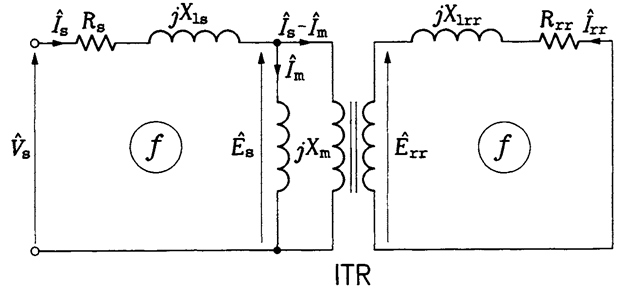
When the rotor is prevented from rotating, the induction motor can be considered to be a three-phase transformer. The iron of the stator and rotor acts as the core, carrying a flux linking the stator and rotor windings, which represent the primary and secondary windings, respectively. The steady-state equivalent circuit of one phase of such a transformer is shown in Figure 2.11. Individual components of the circuit are:
Rs stator resistance
Rn rotor resistance
Xls stator leakage reactance
Xfr rotor leakage reactance
Xm magnetizing reactance
ITR ideal transformer
The phasor notation based on rms values is used for currents and voltages in the equivalent circuit. Specifically,
Vs phasor of stator voltage
Es phasor of stator EMF
E„ phasor of rotor EMF
7S phasor of stator current
I„ phasor of rotor current
7m phasor of magnetizing current
The frequency of these quantities is the same for the stator and rotor and equal to the supply frequency, /. For formal reasons, it is convenient to

FIGURE 2.11 Steady-state equivalent circuit of one phase of the induction motor at standstill.
assume that both the stator and rotor currents enter the ideal transformer, following a sign convention used in the theory of two-port networks.
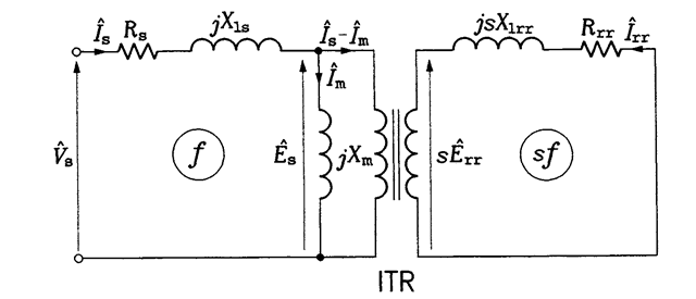
When the rotor revolves freely, the rotor angular speed is lower than that of the magnetic flux produced in the stator by the slip speed, b)sl. As a result, the frequency of currents generated in rotor conductors is sf, and the rotor leakage reactance and induced EMF are sX^ and sE^ respectively. The difference in stator and rotor frequencies makes the corresponding equivalent circuit, shown in Figure 2.12, inconvenient for analysis. This problem can easily be solved using a simple mathematical trick. Notice that the rms value, of rotor current is given by
![tmp2B7-42_thumb[1] tmp2B7-42_thumb[1]](http://lh6.ggpht.com/_X6JnoL0U4BY/S1hZP_7-dxI/AAAAAAAAH9g/gpHRRgPT5u4/tmp2B742_thumb1_thumb.png?imgmax=800)
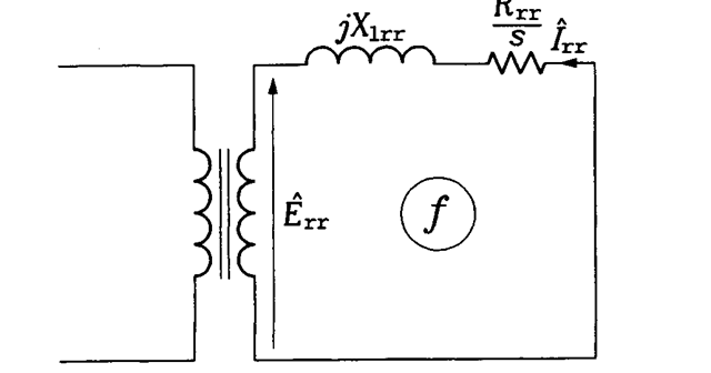
This value will not change when the numerator and denominator of the right-hand side fraction in Eq. (2.7) are divided by s. Then,
![tmp2B7-43_thumb[1] tmp2B7-43_thumb[1]](http://lh3.ggpht.com/_X6JnoL0U4BY/S1hZRHhyiMI/AAAAAAAAH9o/VlRs2h1IrUY/tmp2B743_thumb1_thumb.png?imgmax=800)
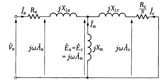
which describes a rotor equivalent circuit shown in Figure 2.13, in which the frequency of rotor current and rotor EMF is / again. In addition, the rotor quantities can be referred to the stator side of the ideal transformer, which allows elimination of this transformer from the equivalent circuit of the motor. The resultant final version of the circuit is shown in Figure

FIGURE 2.12 Per-phase equivalent circuit of a rotating induction motor with different frequencies of the stator and rotor currents.

FIGURE 2.13 Transformed rotor part of the per-phase equivalent circuit of a rotating induction motor.
2.14, in which Ev 7P Rp and Xlp denote rotor EMF, current, resistance, and leakage reactance, respectively, all referred to stator.
In addition to the voltage and current phasors, time derivatives of magnetic flux phasors are also shown in the equivalent circuit in Figure 2.14. They are obtained by multiplying a given flux phasor by jw. Generally, three fluxes (strictly speaking, flux linkages) can be distinguished: the stator flux, As, airgap flux, Am, and rotor flux, Ar They differ from each other only by small leakage fluxes. The airgap flux is reduced in comparison with the stator flux by the amount of flux leaking in the stator; and, with respect to the airgap flux, the rotor flux is reduced by the amount of flux leaking in the rotor.
To take into account losses in the iron of the stator and rotor, an extra resistance can be connected in parallel with the magnetizing reactance.

FIGURE 2.14 Per-phase equivalent circuit of the induction motor with rotor quantities referred to the stator.
Except at high values of the supply frequency, these losses have little impact on dynamic performance of the induction motor. Therefore, throughout the topic, the iron losses, as well as the mechanical losses (friction and windage), are neglected.
It must be stressed that the stator voltage,
Vs, and current, 7S, represent the voltage across a phase winding of stator and the current in this winding, respectively. This means that if the stator windings are connected in wye, Vs is taken as the line-to-neutral (phase) voltage phasor and 7S as the line current phasor. In case of the delta connection, Vs is meant as the line-to-line voltage phasor and 7S as the phase current.
Although the rotor resistance and leakage reactance referred to stator are theoretical quantities and not real impedances, they can directly be found from simple no-load and blocked-rotor tests. See Section 10.4 for a brief description of these tests.
