2.1
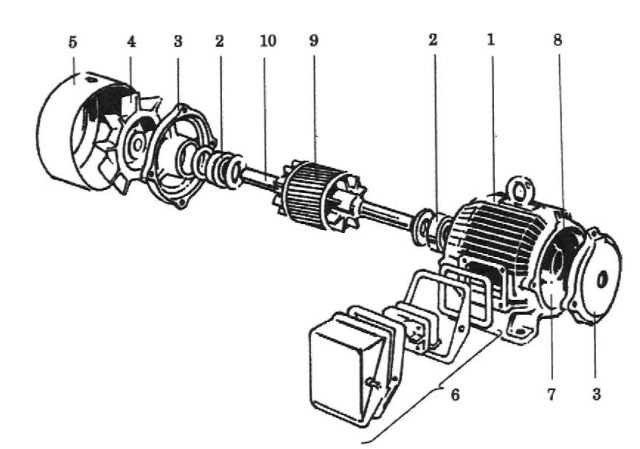
An induction motor consists of many parts, the stator and rotor being the basic subsystems of the machine. An exploded view of a squirrel-cage motor is shown in Figure 2.1. The motor case (frame), ribbed outside for better cooling, houses the stator core with a three-phase winding placed in slots on the periphery of the core. The stator core is made of thin (0.3 mm to 0.5 mm) soft-iron laminations, which are stacked and screwed together. Individual laminations are covered on both sides with insulating lacquer to reduce eddy-current losses. On the front side, the stator housing is closed by a cover, which also serves as a support for the front bearing

FIGURE 2.1 Exploded view of an induction motor: (1) motor case (frame), (2) ball bearings, (3) bearing holders, (4) cooling fan, (5) fan housing, (6) connection box, (7) stator core, (8) stator winding (not visible), (9) rotor, (10) rotor shaft. Courtesy ofDanfoss A/S.
of the rotor. Usually, the cover has drip-proof air intakes to improve cooling. The rotor, whose core is also made of laminations, is built around a shaft, which transmits the mechanical power to the load. The rotor is equipped with cooling fins. At the back, there is another bearing and a cooling fan affixed to the rotor. The fan is enclosed by a fan cover. Access to the stator winding is provided by stator terminals located in the connection box that covers an opening in the stator housing.
Open-frame, partly enclosed,
and totally enclosed motors are distinguished by how well the inside of stator is sealed from the ambient air. Totally enclosed motors can work in extremely harsh environments and in explosive atmospheres, for instance, in deep mines or lumber mills. However, the cooling effectiveness suffers when the motor is tightly sealed, which reduces its power rating.
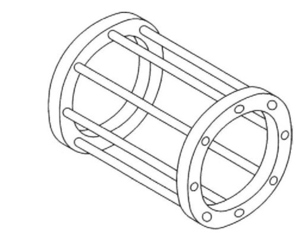
The squirrel-cage rotor winding, illustrated in Figure 2.2,
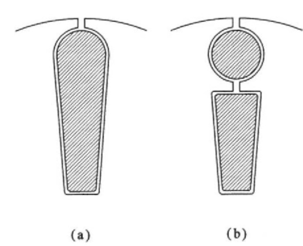
consists of several bars connected at both ends by end rings. The rotor cage shown is somewhat oversimplified, practical rotor windings being made up of more than few bars (e.g., 23), not necessarily round, and slightly skewed with respect to the longitudinal axis of the motor. In certain machines, in order to change the inductance-to-resistance ratio that strongly influences mechanical characteristics of the motor, rotors with deep-bar cages and

FIGURE 2.2 Squirrel-cage rotor winding.

FIGURE 2.3 Cross-section of a rotor bar in (a) deep-bar cage, (b) double cage.
double cages are used. Those are depicted in Figures 2.3a and 2.3b, respectively.
