3.2
As exemplified in Figure 2.18, the stator current at zero slip, that is, the starting current, is typically much higher than the rated current. Using the approximate equivalent circuit in Figure 2.16, the starting current, 7S st, can be estimated as
![tmp2B7-83_thumb[1] tmp2B7-83_thumb[1]](http://lh6.ggpht.com/_X6JnoL0U4BY/S1hdxF-NQRI/AAAAAAAAICk/ZKKeAsXs_Ls/tmp2B783_thumb1_thumb.png?imgmax=800)
In the example motor, the starting current, at about 250 A/ph, is 6.3 times higher than the rated current. For small motors this is usually not a serious issue, and they are started by connecting them directly to the power line. However, large motors, especially those driving loads with high inertia or high low-speed torque, require assisted starting. The following are the most common solutions.
1. In autotransformer starting, illustrated in Figure 3.1, a three-phase autotransformer is controlled using timed relays. The stator

FIGURE 3.1 Autotransformer starting system.
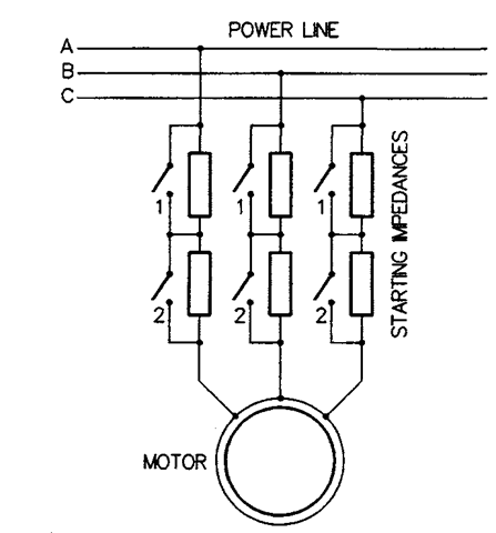
voltage at starting is reduced by shutting contacts 1 and 2, while contacts 3 are open. After a preset amount of time, contacts 1 and 2 are opened and contacts 3 shut. 2. In impedance starting, illustrated in Figure 3.2, series impedances (resistive or reactive) are inserted between the power line and the motor to limit the starting current. As the motor gains speed, the impedances are shorted out, first by contacts 1, then by contacts 2.

FIGURE 3.2 System with starting impedances.
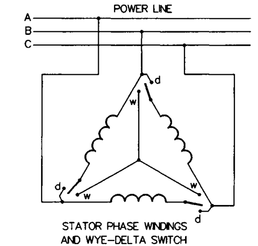
3. In wye-delta starting, illustrated in Figure 3.3, a special switch is used to connect stator phase windings in wye (contacts “w”) when the motor is started and, when the motor is up to speed, to reconnect the windings in delta (contacts “d”). With wye-connected phase windings, the per-phase stator voltage and current are reduced by V3 in comparison with those for delta-connected windings. The wye-delta switch can be controlled manually or automatically.
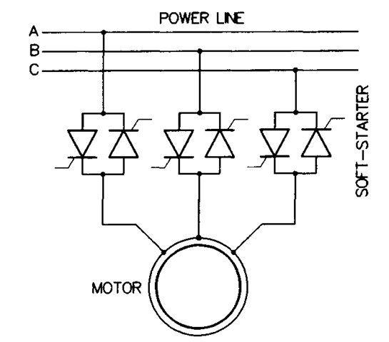
4. In soft-starting, illustrated in Figure 3.4, a three-phase soft-starter based on semiconductor power switches is employed to reduce the stator current. This is done by passing only a part of the voltage waveform and blocking the remaining part. The volt-

FIGURE 3.3 Starting system with the wye-delta switch.

FIGURE 3.4 Soft-starting system.
age and current waveforms are distorted, generating harmonic torques, until, when the motor has gained sufficient speed, the soft-starter connects it directly to the power line. Various starting programs, such as maintaining a constant current or ramping up the voltage, can be realized.
In comparison with the direct online starting, all the preceding methods of assisted starting result in reduction of the starting torque. This, with certain loads, can be a serious disadvantage. As explained later, the variable-frequency starting in ASDs does not have this disadvantage, allowing for high values of the torque.
As an interesting observation, it is worth mentioning that the total energy lost in the rotor during starting is approximately equal to the total kinetic energy of the drive system in the final steady state. This is because the efficiency of power conversion in the rotor is 1 — s. Again, the variable-frequency starting is superior in this respect, because a low slip is consistently maintained.
ASSISTED STARTING (Induction Motor)
Next post: POLE CHANGING (Induction Motor)
Previous post: UNCONTROLLED OPERATION OF INDUCTION MOTORS
