RTCM SC-104 standards for DGPS services
Real-time DGPS operations require the estimation of the pseudorange corrections at the reference receiver, which is then transmitted to the rover receiver through a communication link. To ensure efficiency of operations, the pseudorange corrections are sent in an industry standard format known as the RTCM SC-104 [4]. This format was proposed by the Radio Technical Commission for Maritime Services (RTCM), an advisory organization established in 1947 to investigate issues related to maritime telecommunications. Special Committee No. 104 (SC-104) was established in 1983 to develop recommendations for transmitting differential corrections to GPS users. A draft version of the recommendations was published in November 1985, followed by other updated versions. The most recent version as of this writing, Version 2.2, was published in January 1998 [4]. Originally, the RTCM SC-104 format was designed to support the public marine radio beacon broadcasts of DGPS corrections. However, it has become the industry standard format for transmitting real-time DGPS corrections.
The RTCM SC-104 standards consist of 64 message types [4]. These messages contain information such as the pseudorange correction (PRC) for each satellite in view of the reference receiver, the rate of change of the pseudorange corrections (RRC), and the reference station coordinates. Of interest to the majority of real-time DGPS users are message types 1 and 9. Both contain the PRC and the RRC corrections. However, message type 1 contains the corrections for all the satellites in view of the reference station, while in message type 9 the corrections are packed in groups of three. This leads to a lower latency for message type 9 compared with message type 1, which is useful in the presence of selective availability. The disadvantage of using message type 9, however, is that the reference station requires a more stable clock. Some tentative messages were added in Version 2.2 to support the RTK and differential GLONASS operations. Table 8.1 shows a list of the current message types.
The RTCM SC-104 messages are not directly readable; they are streams of binary digits, zeros and ones. Each RTCM SC-104 message or frame consists of an "N + 2" 30-bit words long; where N represents the number of words containing the actual data within the message and the remaining two words represent a two-word header at the beginning of each message. The size of N varies, depending on the message type and the message content (e.g., the varying number of satellites in view of the reference station).
Table 8.1 Current RTCM Message Types
|
Message Type Number |
Current Status |
Title |
Message Type Number |
Current Status |
Title |
|
1 |
Fixed |
DGPS corrections |
18 |
Fixed |
RTK uncorrected carrier phases |
|
2 |
Fixed |
Delta DGPS corrections |
19 |
Fixed |
RTK uncorrected pseudoranges |
|
3 |
Fixed |
GPS reference station parameters |
20 |
Tentative |
RTK carrier- phase corrections |
|
4 |
Tentative |
Reference station datum |
21 |
Tentative |
RTK/high PRC account |
|
5 |
Fixed |
GPS constellation health |
22 |
Tentative |
Extended reference station parameters |
|
6 |
Fixed |
GPS null frame |
23-30 |
— |
Undefined |
|
7 |
Fixed |
DGPS radio beacon almanac |
31 |
Tentative |
Differential GLONASS corrections |
|
8 |
Tentative |
Pseudolite almanac |
32 |
Tentative |
Differential GLONASS reference standard parameters |
|
9 |
Fixed |
GPS partial correction set |
33 |
Tentative |
GLONASS constellation health |
|
10 |
Reserved |
P-code differential correction |
34 |
Tentative |
GLONASS partial differential correction set |
|
11 |
Reserved |
C/A-code L1, L2 delta corrections |
35 |
Tentative |
GLONASS beacon almanac |
Table 8.1
|
Message Type Number |
Current Status |
Title |
Message Type Number |
Current Status |
Title |
|
12 |
Reserved |
Pseudolite station parameters |
36 |
Tentative |
GLONASS special message |
|
13 |
Tentative |
Ground transmitter parameters |
37 |
Tentative |
GNSS system time offset |
|
14 |
Tentative |
GPS time of week |
38-58 |
— |
Undefined |
|
15 |
Tentative |
Ionospheric delay message |
59 |
Fixed |
Proprietary message |
|
16 |
Fixed |
GPS special message |
60-63 |
Reserved |
Multipurpose usage |
|
17 |
Tentative |
GPS ephemeris |
64 |
— |
Not reported |
The word size and the parity check algorithm are the same as those of the GPS navigation message. The remaining part of this section discusses the structure of message type 1, which is commonly used in real-time DGPS operations.
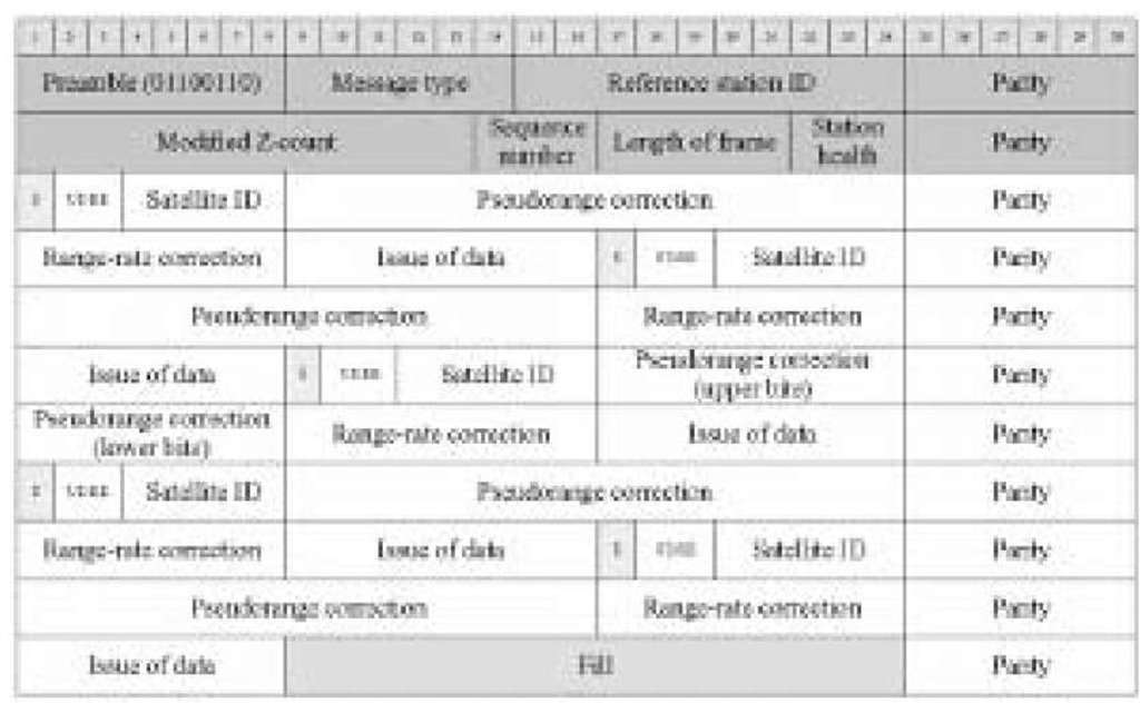
Figure 8.6 shows the structure of a message type 1, where five satellites were visible at the reference station. The first word of the header starts with an 8-bit preamble, which is a fixed sequence 01100110. Following the preamble are 6-bit message type identifier and a 10-bit reference station ID. The last 6 bits of this word and of all other words are assigned for parity, which checks for any error. The second word starts with a 13-bit modified z-count, a time reference for the transmitted message, followed by a 3-bit sequence number for verifying the frame synchronization. The length of frame is assigned bits 17-21 and is used to identify the start of the next frame. Bits 22-24 define the reference station health status; for example, a code of "111" means that the reference station is not working properly. The actual data set for all the satellites is contained in the remaining words. Each satellite requires a total of 40 bits for the correction, distributed in the following sequence: (1) scale factor, S (1 bit); (2) user differential range error, UDRE (2 bits); (3) satellite ID (5 bits); (4) pseudorange correction, PRC (16 bits); (5) range-rate correction, RRC (8 bits); and (6) issue of data (8 bits).
Figure 8.6 Structure of a five-satellite message type 1.
The scale factor is used to scale the PRC/RRC, while the UDRE is a measure of the uncertainty in the PRC. However, the issue of data identifies the GPS navigation message that the reference station used to calculate the satellite position and clock offset. Evidently, there will be cases where the required number of words is not an exact integer number. For example, as shown in Figure 8.6, if the number of satellites in the message is five, 16 bits are required to fill the frame. Similarly, if the number of satellites is four, 8 bits are required to fill the frame. To avoid confusion with the preamble, the fill uses alternating ones and zeros (i.e., 1010101010101010 or 10101010).
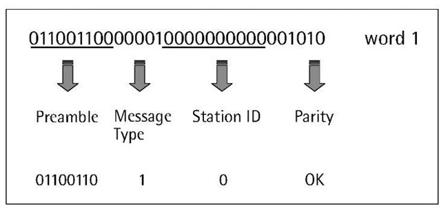
To obtain the DGPS corrections, the transmitted messages must be decoded and converted to 30-bit long words (strings of zeros and ones). Once this is done, party checks should be performed and then the DGPS corrections information can be extracted according to Figure 8.6. Figure 8.7 shows a "real" example showing four type 1 messages; each represents the DGPS corrections for all the satellites in view of the reference station at a particular epoch. Figure 8.8 shows how the first word of the header information is decoded. Most GPS receivers support the RTCM SC-104 standards, which allows the use of different receivers in the real-time mode. It should be noted, however, that not all the differential-ready GPS receivers could output the RTCM standards.
Figure 8.7 Example of raw RTCM SC-104 corrections (message type 1).
Figure 8.8 First-word decoding example.
NMEA 0183 format
NMEA is an acronym for the National Marine Electronics Association, which was founded in 1957 by a group of electronics dealers to strengthen their relationships with electronic manufacturers [5]. In 1983, with input from the manufacturers and private and governmental organizations, the association adopted the NMEA 0183 as a format for interfacing marine electronic devices. It has been updated several times; the latest release, as of this writing, Version 3.0, appeared in July 2000. The NMEA 0183 standards are data streams in the ASCII format, transmitted at a rate of 4,800 bps, from a talker to a listener, where a talker is a device that sends data to other devices (e.g., a GPS receiver) and a listener is a device that receives data from another device (e.g., a laptop computer interfaced with the GPS receiver) [5].
The NMEA 0183 data streams may include information on position, datum, water depth, and other variables. The data is sent in the form of sentences; each starts with a dollar sign "$" and terminates with a carriage return-line feed <CR><LF>. The dollar sign "$" is followed by a five-character address field, which identifies the talker (the first two characters), the data type, and the string format of the successive fields (the last three characters). The last field in any sentence is a checksum field, which follows a checksum delimiter character "*". The maximum total number of characters in any sentence is 82; that is, a maximum of 79 characters between the starting delimiter "$" and the terminating <CR><LF>. A number of these sentences are dedicated to GPS and GLONASS systems, while the remaining sentences support other devices such as echo sounders, gyros, and others [5].
Our discussion will be restricted to one sentence only, the GGA: Global Positioning System fix data. This sentence represents the time and position, and solution-related information. Figure 8.9 shows the general structure of the GGA sentence, while Table 8.2 explains the terms of the sentence.
Figure 8.9 General structure of a GGA sentence.
Table 8.2 Explanation of GGA Sentence Terms
Table 8.2
Most GPS receivers available on the market support the NMEA 0183 standards. However, not all receivers with the NMEA 0183 port output all the GPS-specific messages. In addition, some GPS receiver manufacturers may slightly change the standard format. However, they typically provide software to interpret the data sentence.


