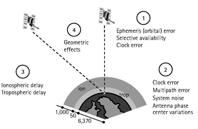
GPS pseudorange and carrier-phase measurements are both affected by several types of random errors and biases (systematic errors). These errors may be classified as those originating at the satellites, those originating at the receiver, and those that are due to signal propagation (atmospheric refraction) [1]. Figure 3.1 shows the various errors and biases.
The errors originating at the satellites include ephemeris, or orbital, errors, satellite clock errors, and the effect of selective availability. The latter was intentionally implemented by the U.S. DoD to degrade the autonomous GPS accuracy for security reasons. It was, however, terminated at midnight (eastern daylight time) on May 1, 2000 [2]. The errors originating at the receiver include receiver clock errors, multipath error, receiver noise, and antenna phase center variations. The signal propagation errors include the delays of the GPS signal as it passes through the ionospheric and tropospheric layers of the atmosphere. In fact, it is only in a vacuum (free space) that the GPS signal travels, or propagates, at the speed of light.
In addition to the effect of these errors, the accuracy of the computed GPS position is also affected by the geometric locations of the GPS satellites as seen by the receiver. The more spread out the satellites are in the sky, the better the obtained accuracy (Figure 3.1).
Figure 3.1 GPS errors and biases.
For example, combining L1 and L2 observables removes, to a high degree of accuracy, the effect of the ionosphere. Mathematical modeling of these errors and biases is also possible. In this topic, the main GPS error sources are introduced and the ways of treating them are discussed.
GPS ephemeris errors
Satellite positions as a function of time, which are included in the broadcast satellite navigation message, are predicted from previous GPS observations at the ground control stations. Typically, overlapping 4-hour GPS data spans are used by the operational control system to predict fresh satellite orbital elements for each 1-hour period. As might be expected, modeling the forces acting on the GPS satellites will not in general be perfect, which causes some errors in the estimated satellite positions, known as ephemeris errors. Nominally, an ephemeris error is usually in the order of 2m to 5m, and can reach up to 50m under selective availability [3]. According to [2], the range error due to the combined effect of the ephemeris and the satellite clock errors is of the order of 2.3m [1s-level; s is the standard deviation.
An ephemeris error for a particular satellite is identical to all GPS users worldwide [4]. However, as different users see the same satellite at different view angles, the effect of the ephemeris error on the range measurement, and consequently on the computed position, is different. This means that combining (differencing) the measurements of two receivers simultaneously tracking a particular satellite cannot totally remove the ephemeris error. Users of short separations, however, will have an almost identical range error due to the ephemeris error, which can essentially be removed through differencing the observations. For relative positioning,the following rule of thumb gives a rough estimate of the effect of the ephemeris error on the baseline solution: the baseline error / the baseline length = the satellite position error / the range satellite [5]. This means that if the satellite position error is 5m and the baseline length is 10 km, then the expected baseline line error due to ephemeris error is approximately 2.5 mm.
Some applications, such as studies of the crustal dynamics of the earth, require more precise ephemeris data than the broadcast ephemeris. To support these applications, several institutions [e.g., the International GPS Service for Geodynamics (IGS), the U.S. National Geodetic Survey (NGS), and Geomatics Canada] have developed postmission precise orbital service. Precise ephemeris data is based on GPS data collected at a global GPS network coordinated by the IGS. At the present time, precise ephemeris data is available to users with some delay, which varies from 12 hours for the IGS ultra rapid orbit to about 12 days for the most precise IGS precise orbit. The corresponding accuracies for the two precise orbits are in the order of a few decimeters to 1 decimeter, respectively. Users can download the precise ephemeris data free of charge from the IGS center, at ftp://igscb.jpl.nasa.gov/igscb/product/.
Selective availability
GPS was originally designed so that real-time autonomous positioning and navigation with the civilian C/A code receivers would be less precise than military P-code receivers. Surprisingly, the obtained accuracy was almost the same from both receivers. To ensure national security, the U.S. DoD implemented the so-called selective availability (SA) on Block II GPS satellites to deny accurate real-time autonomous positioning to unauthorized users. SA was officially activated on March 25, 1990 [3].
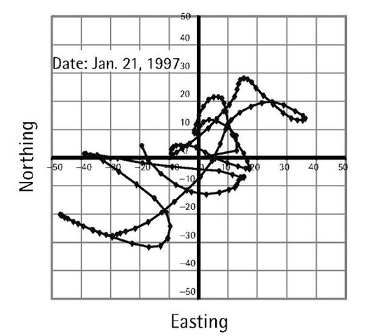
SA introduces two types of errors [6]. The first one, called delta error, results from dithering the satellite clock, and is common to all users worldwide. The second one, called epsilon error, is an additional slowly varying orbital error. With SA turned on, nominal horizontal and vertical errors can be up to 100m and 156m, respectively, at the 95% probability level. Figure 3.2 shows how the horizontal position of a stationary GPS receiver varies over time, mainly as a result of the effect of SA. Like the range error due to ephemeris error, the range error due to epsilon error is almost identical between users of short separations. Therefore, using differential GPS would overcome the effect of the epsilon error. In fact, DGPS provides better accuracy than the standalone P-code receiver due to the elimination or the reduction of the common errors, including SA [4].
Following extensive studies, the U.S. government discontinued SA on May 1,2000, resulting in a much-improved autonomous GPS accuracy [2]. With the SA turned off, the nominal autonomous GPS horizontal and vertical accuracies would be in the order of 22m and 33m (95% of the time), respectively.
Figure 3.2 Position variation of a stationary GPS receiver due to SA.
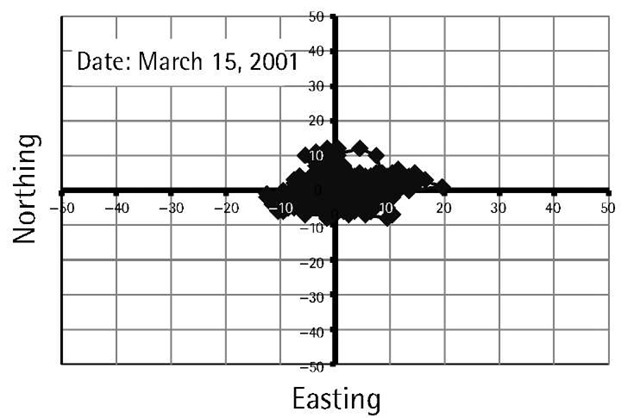
Figure 3.3 shows the GPS errors after SA was turned off. The elimination of SA will open the door for faster growth of GPS markets (e.g., vehicle navigation and enhanced-911). Although the removal of SA would have little impact on the DGPS accuracy, it would reduce the cost of installing and operating a DGPS system. This is mainly because of the reduction in the required transmission rate.
Satellite and receiver clock errors
Each GPS Block II and Block IIA satellite contains four atomic clocks, two cesium and two rubidium [7]. The newer generation Block IIR satellites carry rubidium clocks only. One of the onboard clocks, primarily a cesium for Block II and IIA, is selected to provide the frequency and the timing requirements for generating the GPS signals. The others are backups [7].
The GPS satellite clocks, although highly accurate, are not perfect. Their stability is about 1 to 2 parts in 1013 over a period of one day. This means that the satellite clock error is about 8.64 to 17.28 ns per day. The corresponding range error is 2.59m to 5.18m, which can be easily calculated by multiplying the clock error by the speed of light (i.e., 299,729,458 m/s). Cesium clocks tend to behave better over a longer period of time compared with rubidium clocks. In fact, the stability of the cesium clocks over a period of 10 days or more improves to several parts in 1014 [7].
Figure 3.3 Position variation of a stationary GPS receiver after terminating SA.
The performance of the satellite clocks is monitored by the ground control system. The amount of drift is calculated and transmitted as a part of the navigation message in the form of three coefficients of a second-degree polynomial [3, 8].
Satellite clock errors cause additional errors to the GPS measurements. These errors are common to all users observing the same satellite and can be removed through differencing between the receivers. Applying the satellite clock correction in the navigation message can also correct the satellite clock errors. This, however, leaves an error of the order of several nanoseconds, which translates to a range error of a few meters (one nanosecond error is equivalent to a range error of about 30 cm) [4].
GPS receivers, in contrast, use inexpensive crystal clocks, which are much less accurate than the satellite clocks [1]. As such, the receiver clock error is much larger than that ofthe GPS satellite clock. It can, however, be removed through differencing between the satellites or it can be treated as an additional unknown parameter in the estimation process. Precise external clocks (usually cesium or rubidium) are used in some applications instead of the internal receiver clock. Although the external atomic clocks have superior performance compared with the internal receiver clocks, they cost between a few thousand dollars for the rubidium clocks to about $20,000 for the cesium clocks.
Multipath error
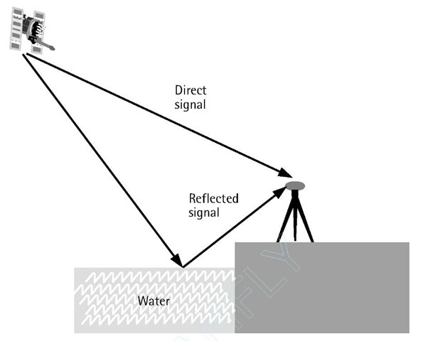
Multipath is a major error source for both the carrier-phase and pseu-dorange measurements. Multipath error occurs when the GPS signal arrives at the receiver antenna through different paths [5]. These paths can be the direct line of sight signal and reflected signals from objects surrounding the receiver antenna (Figure 3.4).
Multipath distorts the original signal through interference with the reflected signals at the GPS antenna. It affects both the carrier-phase and pseudorange measurements; however, its size is much larger in the pseu-dorange measurements. The size of the carrier-phase multipath can reach a maximum value of a quarter of a cycle (about 4.8 cm for the L1 carrier phase). The pseudorange multipath can theoretically reach several tens of meters for the C/A-code measurements. However, with new advances in receiver technology, actual pseudorange multipath is reduced dramatically.
Figure 3.4 Multipath effect.
Examples of such technologies are the Strobe correlator (Ashtech, Inc.) and the MEDLL (NovAtel, Inc.). With these multipath-mitigation techniques, the pseudorange multipath error is reduced to several meters, even in a highly reflective environment [9].
Under the same environment, the presence of multipath errors can be verified using a day-to-day correlation of the estimated residuals [3]. This is because the satellite-reflector-antenna geometry repeats every sidereal day. However, multipath errors in the undifferenced pseudorange measurements can be identified if dual-frequency observations are available. A good general multipath model is still not available, mainly because of the variant satellite-reflector-antenna geometry. There are, however, several options to reduce the effect of multipath. The straightforward option is to select an observation site with no reflecting objects in the vicinity of the receiver antenna. Another option to reduce the effect of multipath is to use a chock ring antenna (a chock ring device is a ground plane that has several concentric metal hoops, which attenuate the reflected signals). As the GPS signal is right-handed circularly polarized while the reflected signal is left-handed, reducing the effect of multipath may also be achieved by using an antenna with a matching polarization to the GPS signal (i.e., right-handed). The disadvantage of this option, however, is that the polarization of the multipath signal becomes right-handed again if it is reflected twice [9].
Antenna-phase-center variation
The point at which the GPS signal is received is called the antenna phase center [3]. Generally, the antenna phase center does not coincide with the physical (geometrical) center of the antenna. It varies depending on the elevation and the azimuth of the GPS satellite as well as the intensity of the observed signal. As a result, additional range error can be expected [3].
The size of the error caused by the antenna-phase-center variation depends on the antenna type, and is typically in the order of a few centimeters. It is, however, difficult to model the antenna-phase-center variation and, therefore, care has to be taken when selecting the antenna type [1]. For short baselines with the same types of antennas at each end, the phase-center error can be canceled if the antennas are oriented in the same direction [11]. Mixing different types of antennas or using different orientations will not cancel the error. Due to its rather small size, this error is neglected in most of the practical GPS applications.
It should be pointed out that phase-center errors could be different on L1 and L2 carrier-phase observations. This can affect the accuracy of the ionosphere free linear combination, particularly when observing short baselines. As mentioned before, for short baselines, the errors are highly correlated over distance and cancel sufficiently through differencing. Therefore, using a single frequency might be more appropriate for short baselines in the static mode.


