GPS for land seismic surveying
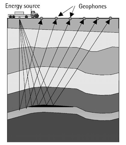
Oil and gas exploration requires mapping of the subsurface geology through seismic surveying. In land seismic surveys, low-frequency acoustic energy is sent down into the underground rock layers (Figure 10.7). The source of the acoustic energy is often selected to be a mechanical vibrator consisting of a metal plate mounted on a truck. The plate is pressed against the ground and vibrated to produce the acoustic energy. In rough areas, dynamite is still being used as the energy source.
As the acoustic energy (signal) crosses the various underground rock layers, it is affected by the physical properties of the rocks. Portions of the signal are reflected back to the surface by the various layers. The reflected energy can be detected by special seismic devices called geophones, which are laid out at known distances from the energy source along the survey line (Figure 10.7). Upon detecting seismic energy, geophones output electrical signals that are proportional to the intensity of the reflected energy [12]. The electrical signals are then recorded on magnetic tapes for geophysical analysis and interpretation.
It is clear that unless the positions of the energy source and the geo-phones are known with sufficient accuracy, the very expensive seismic data becomes useless. GPS is used to provide the positioning information in a standard or a user-defined coordinate system. Integrated GPS/GLONASS and GPS/digital barometer systems have been used successfully in situations of poor GPS signal reception [13]. With the help of GPS, the environmental impacts (e.g., the need to cut trees) as well as the operating cost of seismic surveys have been reduced significantly.
Figure 10.7 GPS for land seismic surveying.
GPS for marine seismic surveying
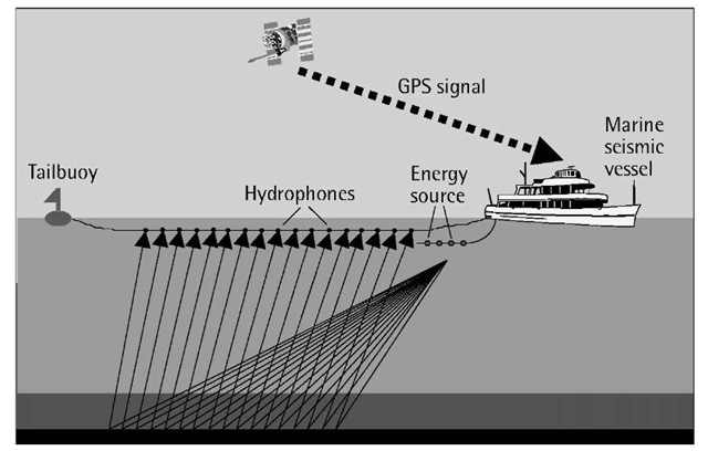
Marine seismic surveying is similar in principle to land seismic surveying. That is, a low-frequency acoustic energy is sent down into the subsurface rock layers, and is reflected back to the surface to reveal information about the composition of subsurface rocks (Figure 10.8).
Different methods are used in marine seismic surveys depending on the water depth. In deep waters, seismic vessels tow seismic cables, known as streamers, which contain devices called hydrophones used for detecting reflected energy. A single vessel will normally tow four to eight parallel streamers; each has a length of several kilometers [12]. The low-frequency acoustic energy is generated using a number of air guns towed behind the vessel at about 6m below the surface.
Figure 10.8 GPS for marine seismic surveying.
In shallow waters, both the land and the marine methods are used. Ocean bottom cable (OBC) survey is a relatively new technology that has been used recently for water depth of up to about 200m. In this method, hydrophones and geophones are combined in a single receiver to avoid water column reverberation (Figure 10.8).
To obtain meaningful results, the positions of the energy source and the hydrophones must be known with sufficient accuracy. This can be easily achieved, at lower cost, with GPS. Moreover, it is possible to revisit the points precisely with the GPS waypoint feature (see Section 10.15).
As the operation of marine seismic surveys is very expensive, the issue of quality control (QC) is essential. To maintain QC, the seismic industry has suggested the use of two independent positioning systems, with GPS being the primary one [12].
GPS for airborne mapping
GPS alone has been successfully used for topographic mapping of small-size areas. Using either conventional GPS kinematic surveying or GPS RTK, a user takes positions of the points on the ground where the topography changes, which can be used at a later time to produce the topographic map of that area. Even in rough areas, GPS can be mounted on all-terrain vehicles (ATVs) to precisely map those areas. However, there exist situations in which the use of GPS alone becomes time-consuming and/or cost-ineffective [14]. Examples include mapping large areas, coastal areas, forests, and inaccessible areas.
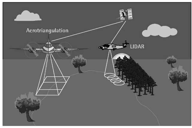
Traditionally, mapping large and inaccessible areas was done using classical airborne photogrammetry. With this method, an aircraft-mounted camera is used to capture a sequence of images for the area to be mapped, which after processing construct the map. To be of practical use, the captured images must first be related to the geodetic reference system (e.g., WGS 84), a process known as georeferencing the images. In classical airborne photogrammetry, the georeferencing is done indirectly with the help of a number of ground control stations with known geodetic coordinates and their corresponding image coordinates. In recent years, GPS has been used onboard the aircraft to provide the precise position of the aerial camera as well as the precise time of each aerial exposure (Figure 10.9) [15].
The use of GPS in airborne photogrammetry has significantly reduced the required number of ground control points. It has not, however, eliminated the necessity for aerial triangulation or the ground control points.
Figure 10.9 GPS for airborne mapping.
This limitation, however, was overcome by augmenting GPS with a high-quality IMU; see Section 9.4 for details about this integration. The integrated GPS/inertial system provides not only the precise position of the imaging sensor but also its orientation (attitude). This allows for the captured images to be directly related to the geodetic reference system without using ground control points. In other words, direct georeferencing of the captured images can be achieved when using an integrated GPS/ inertial system onboard the aircraft. In practice, however, a minimum number of ground control points may be needed for assessing the resulting accuracy [15].
Direct georeferencing using the integrated GPS/inertial system is gaining wide acceptance, and is expected to become the standard tool for rapid determination of the sensor position and orientation. With recent advances in digital airborne imaging sensors and digital photogrammetric workstations, the integrated GPS/inertial system will allow for fully digital photogrammetric workflow to be developed. With digital imaging sensors, no film development and scanning are required, which further reduces the time and the cost of photogrammetric work. Other applications such as airborne remote sensing and light detection and ranging (LIDAR) will greatly benefit from the direct georeferencing using the integrated GPS/inertial system. The latter system, LIDAR, uses an airborne laser scanner to measure the altitude of the points above the ground level [16]. Combining the GPS/inertial-based position and orientation of the laser with the measured altitude of the points leads to direct acquisition of accurate digital elevation models (DEM). Another advantage of the LIDAR system is that the data can be collected at night as well as under cloudy and high wind conditions. In addition, the ability of the laser to penetrate to the ground, even in forest areas, makes the airborne laser system attractive to the forest industry. Moreover, the LIDAR system can be used in mapping featureless areas such as deserts and areas covered by snow and ice [17].
GPS for seafloor mapping
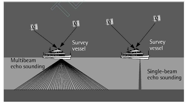
Safe and efficient marine navigation requires, among other factors, accurate information about the water depth and the sea bottom [18]. In addition, the availability of accurate water depth is vital for making use of maximum cargo capabilities. This is especially important for areas with shallow water depth. The traditional way of obtaining the water depth was done using a single-beam echo sounder installed on a survey vessel. With this method, the single-beam echo sounder generates a sounding wave (pulse), which is transmitted to the sea bottom and then reflected back to the echo sounder (see Figure 10.10). The water depth is then computed based on the recorded travel time of the sounding pulse and the velocity of the sound in the water [18]. It should be pointed out that the echo sounder uses a hull-mounted device called the transducer to convert the electrical energy into sound energy and vice versa.
To map an area with a single-beam echo sounder, a survey vessel follows preplanned track lines while the echo sounder generates soundings along the track. Line spacing (the distance between tracks) is selected to provide the best coverage of the area. The accuracy and the reliability of the surveyed depths and locations are verified by supplementing the primary sounding lines by a series of cross lines [18]. This method is characterized by its simplicity. In addition, the echo sounder orientation is not required. A major drawback, however, is that it is time-consuming and does not provide complete coverage of the seafloor.
In recent years, a new technology for seafloor mapping has evolved that combines multibeam echo sounders, GPS, and INS. Multibeam echo sounders employ multiple sounding waves propagating at varying angles, which allow whole swaths of acoustic information to be collected on both sides of the track lines (see Figure 10.10).
Figure 10.10 GPS for seafloor mapping.
Unlike single-beam echo sounders, this multibeam technology offers complete coverage of the seafloor with high resolution, provided that the track lines are optimally designed [19]. Optimal line spacing is determined based on the approximate water depth, the footprint of sound, and the bottom profile. GPS waypoint navigation can be employed in the field to ensure that the vessel follows the designed track lines.
Because of their wide swath (usually 150°), multibeam echo sounders require accurate positioning and attitude of the vessel. This is especially important for the outer beams. Integrated GPS/INS is used for this purpose. Some manufacturers have developed an integrated GPS/INS system that utilizes two GPS receivers and antennas. Besides offering accurate positioning and attitude of the vessel, this integrated system estimates the heading of the vessel at high accuracy regardless of the vessel’s dynamics and latitude.
Another state-of-the-art technology that has found wide acceptance within the hydrographic community is the airborne laser bathymetry system (LBS). LBS operates on the same principle as the land-based airborne laser system, that is, an aircraft-mounted laser sensor transmits a laser beam, which is partially reflected from the sea surface and from the seafloor. The water depth can then be computed by measuring the time difference between the returns of the two reflected pulses. An accurate 3-D seafloor map can be derived from the depth information and the GPS/inertial-based position and orientation of the laser. The major advantages of this method are high productivity and efficiency in mapping difficult areas such as narrow passages. It is, however, limited to shallow water areas (maximum depth about 50m). In addition, it is very sensitive to the water clarity.
GPS for vehicle navigation
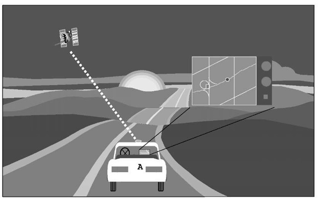
When traveling through unfamiliar areas, vehicle drivers often use paper road maps for route guidance. However, besides being inefficient, searching for a destination using a paper map is unsafe, especially in busy areas. A new technology, incorporating GPS with digital road maps and a computer system, has been developed so that route guidance can be obtained electronically with a touch of a button [20]. Figure 10.11 illustrates this concept.
The role of GPS in this technology is to continuously determine the vehicle’s location. In obstructed areas, such as urban canyons and tunnels, GPS is supplemented by a terrestrial system such as the DR system to overcome the GPS signal blockage. As discussed in Section 9.4, DR is a system that uses the vehicle’s odometer and a selection from accelerometers, compasses, and gyros to determine the vehicle’s direction and traveled distance. This system is accurate only over a short period of time.
The GPS-determined vehicle location is superimposed on an electronic digital road map, containing in its database digital information such as street names and directions, business listings, airports, attractions, and other related information. Once the driver inputs a destination, the built-in computer finds the best route to reach that destination. Factors such as shortest distance and time to destination, one-way roads, illegal turns, and rush-hour restrictions, are all considered in the path finding. Some systems allow the drivers to input other factors such as accident avoidance. The driver usually gets turn-by-turn instructions, with audio and/or visual indications, to the destination. If the driver misses a turn, the system displays a warning message and finds an alternative best route based on the current location of the vehicle.
Figure 10.11 GPS for vehicle navigation.
Some manufacturers add cellular systems to provide weather and traffic information and to locate the vehicles in case of emergency. Recent advances in wireless communication technology even make it possible for drivers to remotely access the Internet from their vehicles [21].
GPS for transit systems
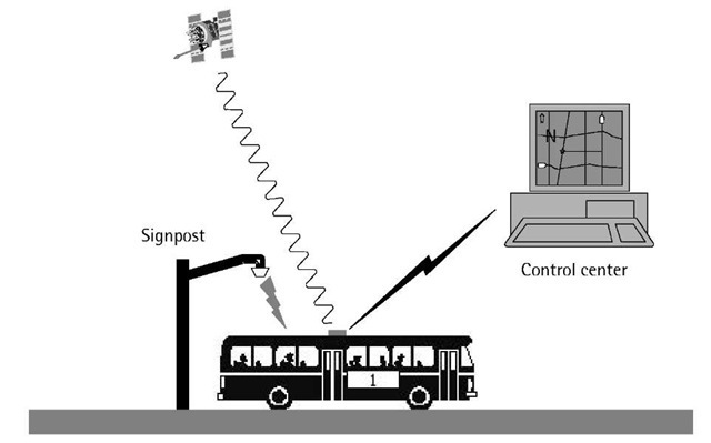
Transit system authorities in many countries are faced with a challenging trend of fiscal constraints, which limits their capabilities to expand existing services and to increase ridership. Until recently, transit systems used old technologies such as odometer/compass sensors and signposts for position determination [22]. Odometers are sensors that measure the number of rotation counts generated by the vehicle’s wheels, which are then used to estimate the distance traveled by the vehicle. With the help of a compass, the vehicle’s direction of travel can be determined at any time. Combining the measurements from the odometer and the compass, the vehicle’s position can be determined with respect to an initial (known) position. Unfortunately, both the odometer and the compass drift over time, which causes significant error in the estimated position. Signposts, in contrast, are radio beacon transmitters that are placed at known locations along the bus routes [23]. Each beacon transmits a low-power microwave signal, which is detected by a receiver on the bus, to account for the odometer’s drift error. Unfortunately, this system has a number of limitations, including its incapability of knowing the exact location of a vehicle in between two signposts. In addition, it is not possible to track a vehicle that goes off-route as a result of, for example, a road closure [22].
To overcome the limitations of these systems, transit authorities are integrating a low-cost autonomous GPS system with one or more of these conventional systems. GPS helps in controlling the drift of the conventional systems through frequent calibration. In addition, the vehicle’s position can be obtained reliably with GPS if the vehicle goes off-route. However, since some of the GPS signals will be obstructed in areas with high-rise buildings, such as downtown areas, the vehicle’s position maybe obtained with the help of conventional systems. As such, the performance of the integrated system is indeed better than either positioning system alone.
The integrated positioning system not only helps the transit authorities to locate their fleet of buses on a digital base map in real time, but also helps in performing other advanced functions (see Figure 10.12). For example, if the bus locations are available in real time, the bus arrival times at the bus stops can be computed reliably, thus minimizing the waiting time at the bus stops. This is a very important feature, especially under severe weather conditions. In addition, the availability of the real-time bus location information enables the transit authorities to dynamically design more efficient bus scheduling, thus improving bus efficiency and customer service. This information can be accessed through the Internet, greatly enhancing customer satisfaction [22].
GPS for the retail industry
In today’s competitive market, efficiency and cost reduction play a significant role in keeping a retailer in business. GPS integrated with a GIS can help in achieving that goal. Other technologies such as wireless data communication and speech recognition are also becoming key components.
Figure 10.12 GPS for transit systems.
This section describes how the different technologies are integrated to ensure efficiency and cost reduction in two components of the retail business: delivery and real-time inventory monitoring.
The integrated system consists of two main components: an efficient route analysis for the delivery area and a GPS-based real-time fleet-monitoring system. In designing an efficient route analysis, it is necessary that an up-to-date digital map (street map database) for the delivery area be available. In addition, retail stores’ location database should also be available. Based on these two sets of databases as well as the traffic conditions, it is possible to optimize the vehicles’ routing and scheduling. A software package such as ESRI’s Arclogistics may be used for that optimization purpose [24]. An optimized real-time fleet-monitoring system requires the availability of both GPS and a suitable wireless data communication. Speech recognition technology may also be used to speed up the delivery service.
To ensure that the GPS-derived position and the map database for the proposed delivery area are compatible, the digital map should be based on WGS 84, the parent datum for GPS. In addition, vector maps rather than raster maps should be used to increase flexibility. Information about driving restrictions, such as one-way streets or vehicle-type restrictions, should accompany the street map database. Retail stores’ location is another database that should also be available. Similar to the street map database, the stores’ location database should be based on WGS 84. Ultimately, the actual network drive times as a function of the time of day should be considered to optimize the route analysis. Other factors that should be considered in the route analysis include order characteristics, delivery time windows, and the varying vehicles’ volume, weight, and operating costs. A good software package should have the capability of using this information to find the best route and stop sequence of each vehicle in the fleet. In addition, the software should have the capability of rerouting a vehicle in cases such as road closure or unexpected heavy traffic due to, for example, accidents. Moreover, the software should have the capability of producing detailed maps with directions to the drivers and a summary report to the dispatching center.
With this optimization process, the routing time would be reduced, which means that the number of vehicles needed for the same service is reduced. This ensures that the delivery cost is reduced. Moreover, as a result of the optimization process, it is expected that the delivery time windows will be reduced as well. This means that goods are delivered more efficiently.
The second main component of the integrated system is a GPS-based real-time fleet-monitoring system. Low-cost standalone GPS receivers may be used, as only low-accuracy positioning information is needed. To avoid GPS signal obstruction, it may be necessary for some vehicles in the fleet that operate in urban areas to be equipped with another, complementary, navigation system such as the DR system [22, 25]. In order for the dispatcher to locate a vehicle in the fleet, it is necessary that the GPS position be sent to the dispatching center via communication link [26]. This could be done in either real time or near real time, depending on the need. In fact, a combination of both might be an ideal solution, if the system is used instate and out-of-state. At each delivery site, the driver may send some information about the products being delivered. Speech-recognition technology could be used to transfer the driver’s voice into digital data that would be sent along with the GPS positioning information. Alternatively, bar codes may be used for the same purpose. The vehicle position should be sent automatically at each delivery site. This may be done by comparing the vehicle’s location and the stored location of the delivery site.
The received vehicles’ position along with other information would be overlaid on a base map, which helps the dispatcher to locate each vehicle in the fleet and to know of its contents. This also helps in making efficient decisions, for example, in case of an emergency. Moreover, better estimates for arrival times, based on the actual vehicles’ location, can be made. If necessary, dynamic rerouting may be done upon receiving new information on the fleet.
Monitoring the fleet as indicated ensures that each driver follows the preassigned route (i.e., it gives the authorities a means for driver accountability). Although this might be a good feature in the system, the driver’s privacy should be considered by, for example, restricting the accessibility of certain information to authorized users.
GPS for cadastral surveying
Cadastral surveys establish property corners, boundaries, and areas of land parcels [6]. Conventional surveying methods have been used, and are still being used, for that purpose. Conventional methods, however, have the drawback that extensive traversing is required. Moreover, extensive clear-cutting and intervening private properties might be required as well. GPS overcomes these conventional-method drawbacks.
Any of the GPS surveying methods, such as kinematic GPS or RTK GPS, can be used depending on the project requirements, location, and other factors. The RTK surveying, however, seems to be the most suitable method, especially in unobstructed areas. This is mainly because of its ease of use and the availability of the results while in the field. Inaccessible locations or obstructed areas can be surveyed with integrated systems such as GPS/LRF or GPS/total station.
There are several advantages of using GPS for cadastral surveying. The most important one is that intervisibility between the points is not required with GPS. This means that extensive traversing is eliminated, clear-cutting is not required, and intervening private properties is avoided. Other advantages include the fact that GPS provides user-defined coordinates in a digital format, which can be easily exported to any GIS system for further analysis. The accuracy obtained with GPS is consistent over the entire network; such accuracy is lacked by conventional surveying methods. Also, with GPS, one reference station can support an unlimited number of rover receivers. A number of governmental and private organizations have reported that the use of GPS in cadastral surveying is cost-effective.
GPS stakeout (waypoint navigation)
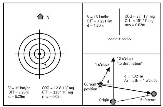
Waypoint navigation, or stakeout as it is called by surveyors, provides guidance to a GPS user in reaching his or her destination in the best way (shortest time and/or distance). By feeding the GPS receiver (or the GPS receiver controller) with the coordinates of his or her destination, a GPS user receives on-screen guidance instantaneously (see Figure 10.13 for details). Surveyors use this principle to lay out points and lines.
The idea behind GPS waypoint navigation is simple. As a first step, the user must feed the GPS receiver (or the GPS controller) with the coordinates of his or her destination. Most GPS receivers are capable of storing a number of destination points (waypoints) in their internal memory. The second step is to let the GPS receiver compute its own position, that is, the user’s positions). Based on the receiver and the destination positions, the built-in receiver computer calculates the distance and the azimuth of the line connecting the receiver’s position and the destination points.
Figure 10.13 GPS waypoint navigation.
The built-in computer uses the position information to calculate other parameters such as the expected arrival time to the user’s destination based on the user’s speed. In addition, the offset distance from the receiver position to the original line between the starting point and the destination can be calculated. All of this information and other data are displayed on a continuous basis to guide the GPS user.
This guidance information can be displayed in different ways [25]. One of these displays is the bull’s-eye, where the destination point is located at the center of the displayed concentric circles while the user’s location is displayed as a moving cursor. The top point of the bull’s-eye is normally selected to represent the north. The user will reach his or her destination point when the moving cursor stays at the center of the concentric circles. In addition to this, a number of navigation parameters are displayed to help the user as well.
