1. Introduction
Extensive applications in genomics and biomedicine remain inaccessible because of the current cost of DNA sequencing technology. Commercial capillary arrays enabled the Human Genome Project but currently define the, often, prohibitive cost structure of sequencing. Microelectromechanical systems (MEMS) have been proposed as one technical approach to a significant near-term advance.
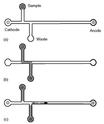
The often-cited intrinsic advantages of the microdevice approach are the practical engineering of cross-channel sample injectors and very high density networks. The basic capability cross-injector is illustrated in Figure 1. Because the volume of sample that is caught in that area is very small, microfabricated devices have the ability to scale the sample consumed in a given experiment far below that of capillary devices.
The cost savings that would accrue from a practical implementation of nanoliter sample handling and injection would be an advance for biological applications. Much research is active in this area. The second main aspect of leverage for microdevice (electrophoretic) sequencing is massively parallel networks that would extend the productivity of systems beyond the, typically 96-lane, capability of commercial capillary arrays. Some substantial capability for MEMS electrophoresis systems was demonstrated in short devices by Paegel et al. (2002) (430-base reads in a compact 96-channel device) and Liu et al. (2000) (450-base reads in a 16-channel device). However, the cost model for de novo sequencing is very sensitive to read length, particularly when assembly costs are considered. Hence, for this application, the compromise in read length in short microdevices (when these devices are compared to capillary instruments) is not acceptable. Short microdevices might be considered for resequencing and genotyping applications. Koutny et al. (2000) demonstrated long read length (800-base reads in a single-channel device), however, in a very simple single-channel device.
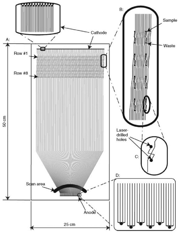
Therefore, although some remarkable capability was demonstrated in the early systems, they did not attempt the combined parallelism, read length, and automation required to challenge the commercial capillary array machines. The current state of the art is now a 768-channel machine, which is in the final stages of testing and which is designed for exactly this purpose. The much more complex microdevice element is illustrated in Figure 2.
Figure 1 Schematic operation of a cross-injector used for DNA sample loading into a typical microdevice. The DNA sample is electrophoresed from the sample well to the waste well traveling, at least in part, through the separation channel. When the optimal loading time has been achieved, the voltages are switched, with the field now applied from one end of the separation channel to the other. This captures the DNA fragments that were in the separation channel at the time of the switch and begins the separation and detection process
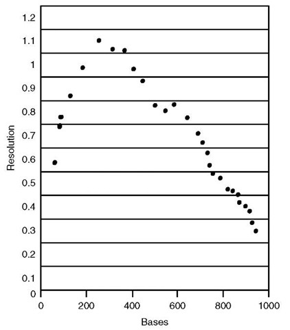
The factors that are most important in microdevice DNA sequencing are resolution and read length (Figure 3). The latter quantity includes consideration of the sample injection timing and the electrophoresis conditions. The ability to identify adjacent DNA fragments, particularly for large fragments, directly determines the performance and throughput characteristics of a given instrument. Because of the central importance of these parameters, each part of the instrument design is affected. The channel architecture cannot be permitted to add significant band broadening, and dense networks need to be robust to instabilities that occur in the network. Hence, the extension of single-channel performance to a dense network is nontrivial for long read applications.
2. Microdevice design and layout
A successful microdevice design must not only optimize conditions for fragment resolution and read length but must also take a number of other factors into account.The device design must have adequate space for the cross-injector elements, must be capable of interfacing with commercial sample introduction instruments (pipettors, capillary arrays, microtiter plates), must have channel separation lengths that allow for high quality, long read performance, and must minimize changes in channel direction, width, and/or cross section to maximize fragment resolution and device lifetime. Several devices have been constructed to this end.
Figure 2 The plates contain 384 channels with double T cross-injectors and separation lengths varying from 37 to 45 cm. As the channels approach the detection window, they curve inward to achieve maximum channel density (~6 lanes/mm) during detection. This design provides full cross-injectors for all lanes, direct compatibility with commercial multitip pipettors, separation lengths optimized for long read performance, and channel geometry, which maximizes separation ability and lifetime
A 16-channel device has been constructed that maintains channel length and minimizes the total size by allowing narrow turns in the device’s separation channels. It has been reported that this device is capable of 450-base high-quality reads (Liu, 2000). Another device, a 96-lane microchip, does not have as extensive separation lengths, but uses a radial design to maximize throughput capability and channel geometry consistency (Paegel, 2002). The 768-lane device mentioned earlier achieves long read length, >580 bases, and increased parallelism by using a large, 50 by 25 cm, substrate for device fabrication.
Figure 3 Resolution curve from a microfabricated single-channel sequencing device comparable to the high-quality performance of capillary machines.
3. Microchip fabrication
These devices are created using standard and slightly modified microfabrication techniques on glass substrates described previously (Becker, 2000). Briefly, the glass substrates are coated with specialized photoresist and patterned via direct-write photolithography. Following this, the channels are etched into and access holes are drilled through the glass. Finally, two pieces of glass substrate are thermally fused.
4. Microchannel coating
Before the electrophoresis stage, the inner surfaces of the channels in the glass microdevice are usually chemically passivated to reduce or eliminate electroos-motic flow. Many different strategies have developed that often rely on the earlier work of Hjerten (1985) to form polymeric coatings for surface modification (Cobb, 1990; Fung, 1995; Madabhushi, 1998). These polymers can be attached to the channel wall either covalently or noncovalently. For glass microdevices, both covalent (Liu, 2000; Woolley, 1997; Shi, 1999) and noncovalent (Simpson, 2000; Backhouse, 2000) methods have been pursued extensively.
5. Separation media
The resolution and read length for a device are largely dependent on the media used for the fragment separation. Linear polyacrylamide (LPA) is used extensively as the separation matrix and is known for having high-quality sequencing ability (Koutny, 2000; Liu, 2000; Paegel, 2002). Several other media have been tested with varying degrees of success including polyethylene oxide (PEO) (Fung, 1995), poly(vinyl pyrrolidone)(PVP) (Song, 2001), hydroxycellulose (HEC) (Bashkin, 1996), and numerous mixed molecular weight and/or self-coating acrylamide copolymers (Sassi, 1996; Menchen, 1996; Dolnik, 2000).
6. Detection
Most microdevices for DNA sequencing use laser-induced fluorescence detection of tagged DNA fragments for detection. Many devices have a modified confocal scanner capable of exciting the fragments and collecting the emitted light (Dolnik, 2000; Woolley, 1997; Shi, 1999; Goedecke et al., 2004). Other detection systems use acousto-optical deflection-based laser beam scanners (Huang, 1999) and CCD cameras (Simpson, 2000).
Because of their inherent advantages, microdevices seem to be the next technological advance in high throughput DNA sequencing. Although there are certain drawbacks, such as the complex electrical networks being created, the sheer potential for parallelism and reduction in reagent costs are enormous.


