Advanced Transmission Techniques
The optical bandwidth available in either of the low-loss transmission windows of the fiber exceeds 1013 Hz. Two ways of taking full advantage of this bandwidth are through the use of ultrashort pulse transmission combined with time-division multiplexing or the use of wavelength/frequency-division multiplexing. Either technique can overcome the limits imposed by the channel dispersion, but both techniques have their limitations. The first technique seeks to turn fiber dispersion to advantage; the second attempts to simply reduce the negative effects of dispersion on a broadband optical signal.
Ultrashort Pulse Transmission. The most common form of multiplexing in digital communication systems is the combination of a number of low data rate signals into a single, high data rate signal by the use of time-division multiplexing. This requires much shorter optical pulses than are used in conventional transmission. As mentioned earlier, the normal (linear) limitation to the data rate is imposed by the fiber attenuation and dispersion. Both of these limits can be exceeded by the use of soliton transmission and optical amplification.
The physics of soliton formation41-45 is discussed in "Nonlinear Optical Properties of Fibers," later in this topic. Solitons, in conjunction with fiber amplifiers, have been shown to promise ultralong distance transmission without the need for optoelectronic repeaters/regenerators. Time-division multiplexing of optical solitons offers the possibility of extremely long distance repeaterless communications.
No communication technique is noise-free, and even solitons amplified by ideal amplifiers will exhibit phase fluctuations which broaden the spectrum and eventually cause the soliton to break up. This spontaneous-emission noise limit is known as the Gordon-Haus limit,46 and had been thought to place a rather severe upper limit on the bit rate distance product for optical fiber systems. It has recently been noted,47 that a unique series of linear filters can prevent the buildup of unwanted phase fluctuations in the soliton, thereby justifying amplified soliton transmission as a viable technology for undersea communications.
Such a communications system puts great demands on the signal processing both at the input and the output. For very high bit rates, one needs either all-optical demultiplexing or extremely fast electronic logic. Current limits on silicon logic are in the range of several Gb/s, which may be adequate for the first implementations of soliton transmission. It is anticipated that all-optical multiplexing and demultiplexing will be required in order to fully exploit the optical fiber bandwidth.
Solitons supported by an optical fiber bear a very specific relationship between pulse width T0, peak power P0, fiber dispersion D, effective area Aeff, and the intensity-dependent refractive index n2. For a lowest-order (N = 1) soliton, ![tmp8-109_thumb[2][2][2][2] tmp8-109_thumb[2][2][2][2]](http://what-when-how.com/wp-content/uploads/2011/09/tmp8109_thumb2222_thumb.png)
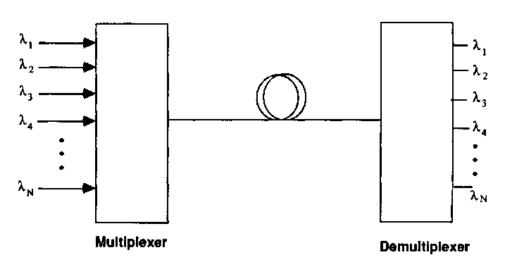
FIGURE 22 Schematic of a WDM transmission system. The main figures of merit are insertion loss (for both the multiplexer and demultiplexer) and channel crosstalk (for the demultiplexer).
Under normal operation, a fiber will propagate lowest-order solitons of about 10 ps in duration. Even for a pulse train of comparatively high duty cycle, this represents less than 100 GHz of a much larger fiber bandwidth. To fully span the bandwidth requires wavelength-division multiplexing.
Wavelength-division Multiplexing (WDM). The troublesome delay between frequencies which is introduced by the fiber dispersion can also be overcome by division of the fiber transmission region into mutually incoherent (uncorrelated) wavelength channels. It is important for these channels to be uncorrelated in order to eliminate any worry about dispersion-induced delay between channels. Figure 22 shows a schematic picture of a WDM transmission system. The concept is quite simple, but reliable implementation can be a considerable challenge.
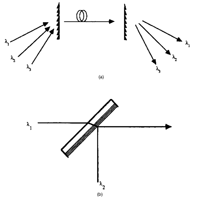
An attractive feature of WDM is the fact that the only active components of the system remain the optical sources and detectors. The multiplexers/demultiplexers are passive and are therefore intrinsically more reliable than active multiplexers. These schemes range from simple refractive/reflective beam combiners to diffractive approaches and are summarized in Fig. 23. For a multiplexing scheme, the key figure of merit is the insertion loss per channel. A simple 50-50 beam splitter for a two-channel combiner offers simple multiplexing with high insertion loss. If the beam splitter is coated to provide high reflectivity at one wavelength and high transmissivity at the other, the insertion loss is reduced, the coupler becomes wavelength-specific, and the element can act either as a multiplexer or demultiplexer.
Grating combiners offer an effective way to maximize the number of channels while still controlling the insertion loss. The grating shape must be appropriately designed—a problem which is easily solved for a single-wavelength, single-angle geometry. However, the diffraction efficiency is a function both of wavelength and angle of incidence. The optimum combination of a range of wavelengths over a wide angular range will typically require a tradeoff between insertion loss, wavelength range, and angular discrimination. Wavelength-division multiplexing technology has been greatly aided by the rapid advances in diffractive optics, synthetic holography, and binary optics in recent years. More on these subjects is included in Chap. 8 of Vol. II.
There have been considerable accomplishments in the past ten years in the fabrication of integrated optical components for WDM applications. Much of these involve the waveguide equivalent of bulk diffractive optical elements.
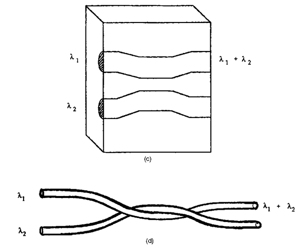
FIGURE 23 Multiplexing/demultiplexing schemes for WDM; (a) grating combiner (bulk optics); (b) wavelength selective beamsplitter (bulk optics); (c) directional coupler (integrated optics); (d) all-fiber multiplexer/demultiplexer.
Since the optical elements are passive and efficient fiber coupling is required, glass waveguides have often been the medium of choice. A great variety of couplers, beam splitters, and multiplexer/demultiplexers have been successfully fabricated in ion-exchanged glass waveguides. Further details on the properties of these waveguides is contained in Chap. 36 of Vol. I. There has also been a major effort to fabricate low-cost polymer-based WDM components. These can be in the form of either waveguides or fibers.
From the point of view of connectivity and modular design, all-fiber WDM components are the most popular. Evanescent single-mode fiber couplers are inherently wavelength-sensitive and can be designed for minimum insertion loss. As with the bulk approaches, all-fiber components become more difficult to design and optimize as the number of channels increases. Most commercially available all-fiber components are designed for widely separated wavelength channels. For example, Corning, Inc. currently offers multiplexers designed for combining signals from 1.5-^m, 1.3-^m, and 0.8-^m sources.
FIGURE 23
Advances in source fabrication technology in recent years have offered the possibility of fabricating diode laser arrays equipped with a controlled gradient in emission wavelength across the array. Such an array, equipped with appropriate beam-combining optics, could greatly reduce the packaging and alignment requirements in a large-scale WDM system. Minimizing crosstalk for closely spaced wavelength channels presents a significant challenge for demultiplexer design.
Coherent Optical Communications. Intensity modulation with direct detection remains the most popular scheme for optical communications systems. Under absolutely ideal transmission and detection conditions (no source RIN, perfect photon-counting detection, no background radiation), the probability of detecting n photons in a pulse train having an average of NP photons per pulse would obey the Poisson distribution
The probability of an "error" PE would be the detection of no photons during the pulse,
If we choose the benchmark error probability of 10-9, we require an average of about 21 photons per pulse. This represents the quantum limit for the direct detection of optical signals. This limit can scarcely be reached, since it assumes no dark count and perfectly efficient photon counting.
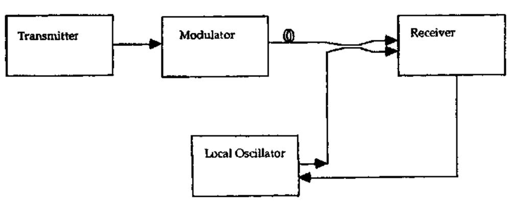
FIGURE 24 Generic coherent optical fiber communication link.
Current optical communication48-54 offers a way to achieve quantum-limited receiver sensitivities even in the presence of receiver noise. By using either amplitude, phase, or frequency modulation combined with heterodyne or homodyne detection, it is possible to approach, and even exceed, the quantum limit for direct detection.
A generic coherent optical communication link is shown in Fig. 24. The crucial differences with direct detection lie in the role of the modulator in transmission and the presence of the local oscillator laser in reception. To understand the role of the modulator, we first consider the method of heterodyne detection. We will then discuss the component requirements for a coherent optical fiber communication link.
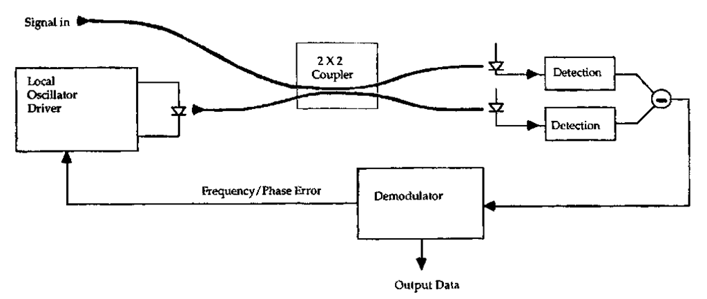
Heterodyne and Homodyne Detection. We consider the receiver shown in Fig. 25, in which an optical signal arriving from some distant point is combined with an intense local oscillator laser by use of a 2 x 2 coupler. The power I(r) guided in the single-mode fiber due to the interfering amplitudes can be expressed as
in which eLO(t) and eS(t) denote the polarizations of the local oscillator and signal, PLO and PS(t) denote the powers of the local oscillator and signal, YS(r) and ^LO(r) are the spatial amplitude distributions, and A^(t) denotes the phase difference between the two sources. The two sources may oscillate at two nominally different frequencies, the difference being labeled the intermediate frequency rnIF (from heterodyne radio nomenclature). If the intermediate frequency is zero, the detection process is termed homodyne detection; if a microwave or radio carrier frequency is chosen for postdetection processing, the detection process is referred to as heterodyne detection.
FIGURE 25 Heterodyne/homodyne receiver.
If the local oscillator power is much larger than the signal power, the first term is negligible. The second represents a large, continuous signal which carries no information but does provide a shot noise contribution. The third term represents the signal information. If the signal is coupled to a detector of responsivity R and ac-coupled to eliminate the local oscillator signal, the photocurrent i(t) can be expressed as follows:
The heterodyne efficiency nHET is determined by the spatial overlap of the fields and the inner product of the polarization components:
These results illustrate four principles of coherent optical fiber communications:
1. The optical frequency and phase of the signal relative to those of the local oscillator are preserved, including the phase and frequency fluctuations.
2. The local oscillator "preamplifies" the signal, yielding a larger information-carrying component of the photocurrent than would be detected directly.
3. The local oscillator and signal fields must occupy the same spatial modes. Modes orthogonal to that of the local oscillator are rejected.
4. Only matching polarization components contribute to the detection process.
The first principle allows the detection of frequency or phase information, provided the local oscillator has sufficient stability. The second provides an improvement of the signal-to-noise ratio in the limit of large local oscillator power. Both the first and fourth lead to component requirements which are rather more stringent than those encountered with direct detection. The following sections will discuss the source, modulator, fiber, and receiver requirements in a coherent transmission system.
Receiver Sensitivity. Let cT represent the receiver noise described in Eq. (26). The signal-to-noise ratio for heterodyne detection may be expressed as
where Bn denotes the noise bandwidth of the receiver. (Bn is generally about half of the data rate for digital systems.) For homodyne detection, the signal envelope carries twice the energy, and
For a given modulation scheme, homodyne detection will therefore be twice as sensitive as heterodyne.
Modulation Formats. The modulation formats appropriate for coherent optical communications can be summarized as follows:
1. Amplitude-Shift Keying (ASK). This technique is simply on-off keying (similar to simple intensity modulation) but with the important constraint that the frequency and phase of the laser be kept constant. Direct modulation of ordinary semiconductor lasers produces a frequency chirp which is unacceptable for ASK modulation. An external modulator such as an electro-optic modulator, a Mach-Zehnder modulator, or an electroabsorption modulator would therefore be appropriate for ASK.
2. Phase-Shift Keying (PSK). This technique requires switching the phase between two or more values. Any phase modulator can be suitable for phase-shift keying. Direct modulation of semiconductor lasers is not suitable for PSK for the same reasons mentioned for ASK.
3. Frequency-Shift Keying (FSK). FSK has received a good deal of attention55 because it can be achieved by direct modulation of the source. It is possible to make use of the natural frequency chirp of the semiconductor laser to frequency modulate the laser simply by a small modulation of the drive current.
All of the modulation techniques can operate between two states (binary) or extend to four or more levels. The only technique which benefits from an increase in the number of channels is FSK. The sensitivity of PSK to source phase noise generally precludes higher-level signaling. Multilevel FSK, being a bandwidth expansion technique, offers a receiver sensitivity improvement over binary FSK without placing severe constraints on the source.
Table 4 gives expressions for the receiver error probability as a function of received power for each modulation technique. The right-hand column gives, for comparison purposes, the number of photons required per pulse to assure an error rate of better than 10-9. PSK modulation with homodyne detection is the most sensitive, requiring only nine photons per pulse, which is below the quantum limit for direct detection.
Source Requirements. One of the ways coherent optical communications systems differ from their microwave counterparts is in the comparatively large phase noise of the source. Since the detection system is sensitive to the frequency and phase of the laser, the source linewidth is a major consideration. This is very different from intensity modulation/direct detection, in which the source spectral width limits the system only through the channel dispersion. When two sources are heterodyned to generate an intermediate frequency in the microwave region, the spectral spread of the heterodyned signal is the combined spectral spread of the signal and local oscillator. Thus, the rule of thumb for high-quality coherent detection is that the sum of the linewidths of the signal and local oscillator be much less than the receiver bandwidth.
TABLE 4 Receiver Sensitivities for a Variety of Modulation/Detection Schemes
|
Modulation/Detection Scheme |
 |
Photons per pulse @ PE = 10-9 |
|
ASK heterodyne |
 |
72 |
|
ASK homodyne |
 |
36 |
|
FSK heterodyne |
 |
36 |
|
PSK heterodyne |
 |
18 |
|
PSK homodyne |
 |
9 |
|
Direction detection quantum limit |
 |
21 |
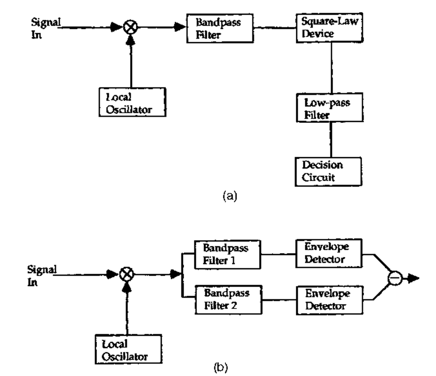
FIGURE 26 Noncoherent (asynchronous) demodulation schemes: (a) ASK envelope detection; (b) FSK dual filter detection, in which the signal is separated into complementary channels for ASK envelope detection.
Precisely how narrow the linewidth must be has been a topic of many papers.49-52 The result varies somewhat with modulation scheme and varies strongly with the demodulation process. The general trends can be summarized as follows:
Incoherent Demodulation (Envelope Detection). Either ASK or FSK can be demodulated simply by using an appropriate combination of filters and nonlinear elements. The basic principle of incoherent ASK or dual-filter FSK detection is illustrated in Fig. 26. This type of detection is, in general, least sensitive to the spectral width of the source. The primary effect of a broad source is to broaden the IF signal spectrum, resulting in attenuation but not a catastrophic increase in bit error rate. Further, the receiver bandwidth can always be broadened to accommodate the signal. This yields a penalty in excess receiver noise, but the source spectral width can be a substantial fraction of the bit rate and still keep the receiver sensitivity within tolerable limits.
There are two approaches to PSK detection which avoid the need for a phase-locked loop. The first is differential phase-shift keying (DPSK), in which the information is transmitted in the form of phase differences between neighboring time slots. The second is phase diversity reception, in which a multiport interferometer is designed to yield signals proportional to the power in different phase quadrants.
Coherent Demodulation with Electronic Phase-Locked Loop. Some PSK signals cannot be demodulated incoherently and require careful receiver design for proper carrier recovery. Suppressed carrier communications schemes such as PSK require a nonlinear recovery circuit. The phase estimation required in proper carrier recovery is far more sensitive to phase noise than is the case with envelope detection. In contrast to incoherent demodulation, source spectral widths must generally be kept to less than 1 percent of the bit rate (10 percent of the phase-locked loop bandwidth) to maintain reliable detection.
Coherent Demodulation with Optoelectronic Phase-Locked Loop. Homodyne detection requires that an error signal be fed back to the local oscillator; phase and frequency errors must be corrected optically in order to maintain precise frequency and phase matching between the two signals. This generally results in a narrower phase-locked loop bandwidth and a much narrower spectral width requirement for the transmitter and local oscillator. Homodyne systems therefore require considerably narrower linewidths than their heterodyne counterparts.
Fiber Requirements. Heterodyne or homodyne reception is inherently single-mode, and it is therefore necessary for coherent links to use single-mode fibers. Single-mode couplers can then be used to combine the signal and local oscillator lasers for efficient heterodyne detection.
As with other forms of fiber communications, fiber dispersion presents a degradation in the signal-to-noise ratio due to differential delay between different components of the signal spectrum. The power penalty associated with fiber dispersion is determined entirely by the dispersion, the fiber length, and the bit rate. Because of the stringent source line width requirements for coherent detection, the spectral broadening is entirely due to the signal itself. The coherent detection system is therefore inherently less sensitive to fiber dispersion.
One important requirement of any fiber that is to be used for coherent transmission is polarization control. As was discussed briefly under "Polarization Characteristics of Fibers" earlier in this topic, the transmitted polarization of light from a single-mode fiber varies randomly with temperature, stress on the fiber, and other environmental influences. If heterodyning is attempted under these circumstances, the heat signal will fade in and out as the polarization of the signal changes.
Polarization fading can be controlled either by external compensation,56 internal control,11 or polarization diversity reception.57 External compensation seeks to actively control the polarization of the output by sensing the error through a polarizer-analyzer combination and feeding back to correct the polarization. The latter can be accomplished through mechanical, electro-optical, or magneto-optical means.
There are classes of optical fiber sensors which have source and fiber requirements very similar to those of a coherent communication link. One of the most widely studied has been the optical fiber gyro, in which counterpropagating waves in a rotating fiber coil interfere with one another; the resulting beat frequency between the waves is proportional to the angular velocity of the coil. There are other interferometric sensors which make use of optical fibers. Most of them require polarization control and a high degree of frequency stability for the source. The relatively low frequencies and small bandwidths which are required for sensing represent the major difference between these applications and coherent data transmission.
![tmp8-112_thumb[2][2][2][2] tmp8-112_thumb[2][2][2][2]](http://what-when-how.com/wp-content/uploads/2011/09/tmp8112_thumb2222_thumb.png)
![tmp8-118_thumb[2][2][2][2] tmp8-118_thumb[2][2][2][2]](http://what-when-how.com/wp-content/uploads/2011/09/tmp8118_thumb2222_thumb.png)
![tmp8-119_thumb[2][2][2][2] tmp8-119_thumb[2][2][2][2]](http://what-when-how.com/wp-content/uploads/2011/09/tmp8119_thumb2222_thumb.png)
![tmp8-120_thumb[2][2][2][2] tmp8-120_thumb[2][2][2][2]](http://what-when-how.com/wp-content/uploads/2011/09/tmp8120_thumb2222_thumb.png)
