INTRODUCTION
Optical fibers were first envisioned as optical elements in the early 1960s. It was perhaps those scientists well-acquainted with the microscopic structure of the insect eye who realized that an appropriate bundle of optical waveguides could be made to transfer an image and the first application of optical fibers to imaging was conceived. It was Charles Kao1 who first suggested the possibility that low-loss optical fibers could be competitive with coaxial cable and metal waveguides for telecommunications applications. It was not, however, until 1970 when Corning Glass Works announced an optical fiber loss less than the benchmark level of 10 dB/km23 that commercial applications began to be realized. The revolutionary concept which Corning incorporated and which eventually drove the rapid development of optical fiber communications was primarily a materials one—it was the realization that low doping levels and very small index changes could successfully guide light for tens of kilometers before reaching the detection limit. The ensuing demand for optical fibers in engineering and research applications spurred further applications. Today we see a tremendous variety of commercial and laboratory applications of optical fiber technology. This topic will discuss important fiber properties, describe fiber fabrication and chemistry, and discuss materials trends and a few commercial applications of optical fiber.
While it is important, for completeness, to include a treatment of optical fibers in any handbook of modern optics, an exhaustive treatment would fill up many volumes all by itself.The interested reader is referred to the "Further Reading" section at the end of this topic for additional reference material.
Optical fiber science and technology relies heavily on both geometrical and physical optics, materials science, integrated and guided-wave optics, quantum optics and optical physics, communications engineering, and other disciplines. Interested readers are referred to other topics within this collection for additional information on many of these topics.
The applications which are discussed in detail in this topic are limited to information technology and telecommunications. Readers should, however, be aware of the tremendous activity and range of applications for optical fibers in metrology and medicine. The latter, which includes surgery, endoscopy, and sensing, is an area of tremendous technological importance and great recent interest. While the fiber design may be quite different when optimized for these applications, the general principles of operation remain much the same. A list of references which are entirely devoted to optical fibers in medicine is listed in "Further Reading."
PRINCIPLES OF OPERATION
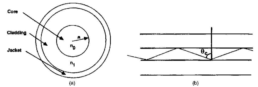
The optical fiber falls into a subset (albeit the most commercially significant subset) of structures known as dielectric optical waveguides. The general principles of optical waveguides are discussed elsewhere in Chap. 6 of Vol. II, "Integrated Optics"; the optical fiber works on principles similar to other waveguides, with the important inclusion of a cylindrical axis of symmetry. For some specific applications, the fiber may deviate slightly from this symmetry; it is nevertheless fundamental to fiber design and fabrication. Figure 1 shows the generic optical fiber design, with a core of high refractive index surrounded by a low-index cladding. This index difference requires that light from inside the fiber which is incident at an angle greater than the critical angle
be totally internally reflected at the interface. A simple geometrical picture appears to allow a continuous range of internally reflected rays inside the structure; in fact, the light (being a wave) must satisfy a self-interference condition in order to be trapped in the waveguide. There are only a finite number of paths which satisfy this condition; these are analogous to the propagating electromagnetic modes of the structure. Fibers which support a large number of modes (these are fibers of large core and large numerical aperture) can be adequately analyzed by the tools of geometrical optics; fibers which support a small number of modes must be characterized by solving Maxwell’s equations with the appropriate boundary conditions for the structure.
FIGURE 1 (a) Generic optical fiber design, (b) path of a ray propagating at the geometric angle for total internal reflection.
FIGURE 2 Ray path in a gradient-index fiber.
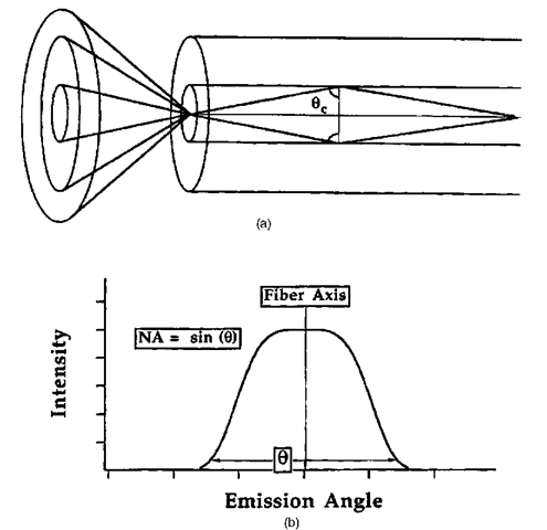
Fibers which exhibit a discontinuity in the index of refraction at the boundary between the core and cladding are termed step-index fibers. Those designs which incorporate a continuously changing index of refraction from the core to the cladding are termed gradient-index fibers. The geometrical ray path in such fibers does not follow a straight line—rather it curves with the index gradient as would a particle in a curved potential (Fig. 2). Such fibers will also exhibit a characteristic angle beyond which light will not internally propagate. A ray at this angle, when traced through the fiber endface, emerges at an angle in air which represents the maximum geometrical acceptance angle for rays entering the fiber; this angle is the numerical aperture of the fiber (Fig. 3). Both the core size and numerical aperture are very important when considering problems of fiber-fiber or laser-fiber coupling. A larger core and larger numerical aperture will, in general, yield a higher coupling efficiency. Coupling between fibers which are mismatched either in core or numerical aperture is difficult and generally results in excess loss.
FIGURE 3 The numerical aperture of the fiber defines the range of external acceptance angles.
FIGURE 4 Classification of geometrical ray paths in an optical fiber. (a) Meridional ray; (b) leaky ray; (c) ray corresponding to a cladding mode; (d) skew ray.
The final concept for which a geometrical construction is helpful is ray classification. Those geometrical paths which pass through the axis of symmetry and obey the self-interference condition are known as meridional rays. There are classes of rays which are nearly totally internally reflected and may still propagate some distance down the fiber. These are known as leaky rays (or modes). Other geometrical paths are not at all confined in the core, but internally reflect off of the cladding-air (or jacket) interface. These are known as cladding modes. Finally, there exists a class of geometrical paths which are bound, can be introduced outside of the normal numerical aperture of the fiber, and do not pass through the axis of symmetry. These are often called skew rays. Figure 4 illustrates the classification of geometrical paths.
Geometrical optics has a limited function in the description of optical fibers, and the actual propagation characteristics must be understood in the context of guided-wave optics. For waveguides such as optical fibers which exhibit a small change in refractive index at the boundaries, the electric field can be well described by a scalar wave equation,
the solutions of which are the modes of the fiber.![]() is generally assumed to be separable in the variables of the cylindrical coordinate system of the fiber:
is generally assumed to be separable in the variables of the cylindrical coordinate system of the fiber:
This separation results in the following eigenvalue equation for the radial part of the scalar field:
in which m denotes the azimuthal mode number, and P is the propagation constant. The solutions must obey the necessary continuity conditions at the core-cladding boundary. In addition, guided modes must decay to zero outside the core region. These solutions are readily found for fibers having uniform, cylindrically symmetric regions but require numerical methods for fibers lacking cylindrical symmetry or having an arbitrary index gradient. A common form of the latter is the so-called a-profile in which the refractive index exhibits the radial gradient.4
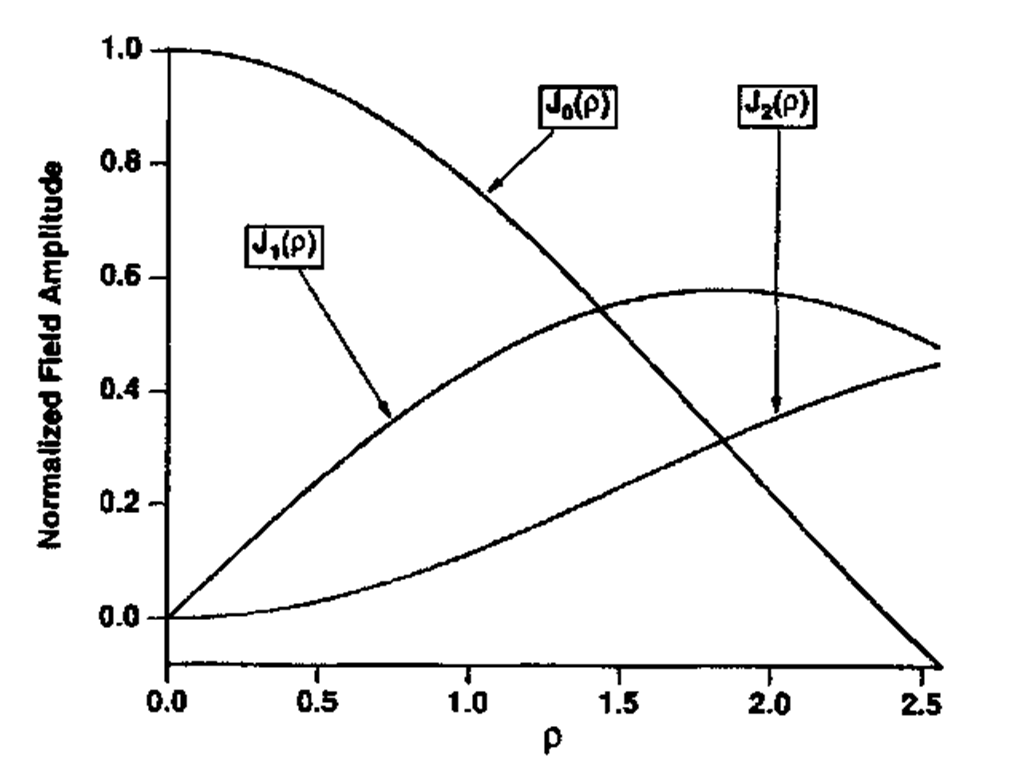
FIGURE 5 Bessel functions
The step-index fiber of circular symmetry is a particularly important case, because analytic field solutions are possible and the concept of the "order" of a mode can be illustrated. For this case, the radial dependence of the refractive index is the step function
The solutions to this are Bessel functions5 and are illustrated in Fig. 5. It can be seen that only the lowest-order mode (m = 0) has an amplitude maximum at the center. Its solution in the (core) propagating region (r < a) is
while the solution in the cladding (r > a) is the modified Bessel function
Higher-order modes will have an increasing number of zero crossings in the cross section of the field distribution.
Fibers which allow more than one bound solution for each polarization are termed multi-mode fibers. Each mode will propagate with its own velocity and have a unique field distribution. Fibers with large cores and high numerical apertures will typically allow many modes to propagate. This often allows a larger amount of light to be transmitted from incoherent sources such as light-emitting diodes (LEDs). It typically results in higher attenuation and dispersion, as discussed in the following section.
By far the most popular fibers for long distance telecommunications applications allow only a single mode of each polarization to propagate. Records for low dispersion and attenuation have been set using single-mode fibers, resulting in length-bandwidth products exceeding 10 Gb-km/s. In order to restrict the guide to single-mode operation, the core diameter must typically be 10 |im or less. This introduces stringent requirements for connectors and splices and increases the peak power density inside the guide. As will be discussed, this property of the single-mode fiber enhances optical nonlinearities which can act to either limit or increase the performance of an optical fiber system.
Attenuation
In most cases, the modes of interest exhibit a complex exponential behavior along the direction of propagation z.
P is generally termed the propagation constant and may be a complex quantity. The real part of P is proportional to the phase velocity of the mode in question, and produces a phase shift on propagation which changes rather rapidly with optical wavelength. It is often expressed as an effective refractive index for the mode by normalizing to the vacuum wave vector:
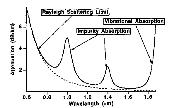
The imaginary part of P represents the loss (or gain) in the fiber and is a weak (but certainly not negligible) function of optical wavelength. Fiber attenuation occurs due to fundamental scattering processes (the most important contribution is Rayleigh scattering), absorption (both the OH-absorption and the long-wavelength vibrational absorption), and scattering due to inhomogeneities arising in the fabrication process. Attenuation limits both the short-and long-wavelength applications of optical fibers. Figure 6 illustrates the attenuation characteristics of a typical fiber.
The variation of the longitudinal propagation velocity with either optical frequency or path length introduces a fundamental limit to fiber communications. Since signaling necessarily requires a nonzero bandwidth, the dispersion in propagation velocity between different frequency components of the signal or between different modes of a multimode fiber produces a signal distortion and intersymbol interference (in digital systems) which is unacceptable. Fiber dispersion is commonly classified as follows.
Intermodal Dispersion
The earliest telecommunications links as well as many modern data communications systems have made use of multimode fiber. These modes (which we have noted have some connection to geometrical ray angles) will typically have a broad range of propagation velocities. An optical pulse which couples to this range of guided modes will tend to broaden by an amount equal to the mean-squared difference in propagation time among the modes.
FIGURE 6 Attenuation characteristics of a typical fiber: (a) schematic, showing the important mechanisms of fiber attenuation.
This was the original purpose behind the gradient-index fiber; the geometrical illustrations of Figs. 1 and 2 show that, in the case of a step-index fiber, a higher-order mode (one with a steeper geometrical angle or a higher mode index m) will propagate by a longer path than an axial mode. A fiber with a suitable index gradient will support a wide range of modes with nearly the same phase velocity. Vassell was among the first to show this,6 and demonstrated that a hyperbolic secant profile could very nearly equalize the velocity of all modes. The a-profile description eventually became the most popular due to the analytic expansions it allows (for certain values of a) and the fact that it requires the optimization of only a single parameter.
Multimode fibers are no longer used in long distance (>10 km) telecommunications due to the significant performance advantages offered by single-mode systems. Many short-link applications, for which intermodal dispersion is not a problem, still make use of multimode fibers.
Material Dispersion
The same physical processes which introduce fiber attenuation also produce a refractive index which varies with wavelength. This intrinsic, or material, dispersion is primarily a property of the glass used in the core, although the dispersion of the cladding will influence the fiber in proportion to the fraction of guided energy which actually resides outside the core. Material dispersion is particularly important if sources of broad spectral width are used, but narrow linewidth lasers which are spectrally broadened under modulation also incur penalties from material dispersion. For single-mode fibers, material dispersion must always be considered along with waveguide and profile dispersion.
Waveguide and Profile Dispersion
The energy distribution in a single-mode fiber is a consequence of the boundary conditions at the core-cladding interface, and is therefore a function of optical frequency. A change in frequency will therefore change the propagation constant independent of the dispersion of the core and cladding materials; this results in what is commonly termed waveguide dispersion. Since dispersion of the core and cladding materials differs, a change in frequency can result in a small but measurable change in index profile, resulting in profile dispersion (this contribution, being small, is often neglected). Material, waveguide, and profile dispersion act together, the waveguide dispersion being of opposite sign to that of the material dispersion. There exists, therefore, a wavelength at which the total dispersion will vanish. Beyond this, the fiber exhibits a region of anomalous dispersion in which the real part of the propagation constant increases with increasing wavelength. Anomalous dispersion has been used in the compression of pulses in optical fibers and to support long distance soliton propagation.
Dispersion, which results in a degradation of the signal with length, combines with attenuation to yield a length limit for a communications link operating at a fixed bandwidth. The bandwidth-length product is often cited as a practical figure of merit which can include the effects of either a dispersion or attenuation limit.


