FINITE ELEMENT ANALYSIS
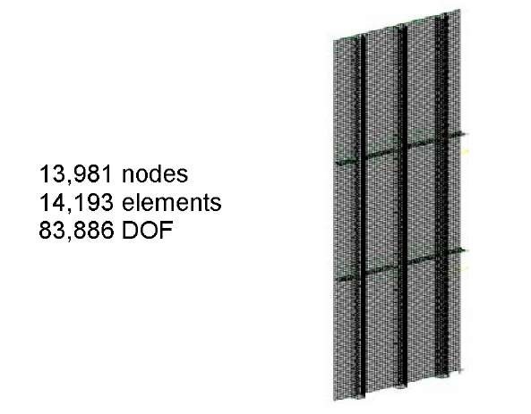
An analytical evaluation of each panel was conducted using the computer code STAGS [3]. The finite element model for the hat-stiffened panel is shown in figure 7. The others used a similar mesh with similar numbers of elements. The hat-stiffened panel model included 13,656 quadrilateral shell elements representing the skin, flanges, hats, and frames. The foam inside the hats in all three panels was modeled as part of the shell elements representing the hat tops and webs. This assumption was adequate since the foam carried a negligible amount of load but restrained buckling of the hat webs. For all three panels, the material properties are based on the compression properties for a stack of material [1], such that the stack axial stiffness is 63.6 GPa, the lateral stiffness is 32.1 GPa, the shear stiffness is 15.6 GPa, and Poisson’s ratio is 0.397. In addition, the pultruded rods were modeled as beam elements with axial stiffness 124 GPa for both rod-stiffened panels.
Fig 6 Vision Image Correlation System.
Fig 7 Finite element model of the hat-stiffened panel.
The loaded ends of each panel inside the potting were restrained by forcing all lateral and out-of-plane displacements to be zero inside the potted region. Frame supports were not included as restraints in the analyses since test data indicates that the frames moved out-of-plane during loading. Two types of edge restraint assumptions were used for each panel. First, the unloaded edges were restrained such that no out-of-plane motion was permitted but all other degrees of freedom were allowed. Second, no edge restraint was included, allowing the unloaded edge to deform in any direction.
RESULTS AND DISCUSSION
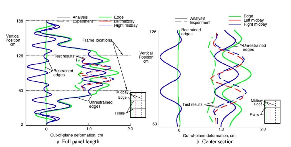
The experimental full-field deformation in the center region between frames for the hat-stiffened panel is shown in figure 8 for a load level of approximately 640 kN, which is immediately prior to the failure load of 641.7 kN. The edges of the panel display an out-of-plane deformation of approximately 0.9 cm despite the presence of the edge restraints. Lines of data for out-of-plane motion near the left edge, and midbay between hats were extracted from the VIC data and plotted in figure 9 as a function of vertical position. Frame locations are indicated by the light black dashed lines. Out-of-plane deformations along the left edge and midbay between hats from test and the two analyses of the hat-stiffened panel are shown in figure 9a for the full panel length, and in figure 9b for the center section between frames, for a load of approximately 640 kN. The analytical results show the full panel length and are represented by solid lines, while test results were only obtained between two center frames and are shown as dashed lines. Panel edge deformations are shown in green lines, and left and right midbay deformations are shown in red and blue lines, respectively. Since the panel is symmetric, the analysis indicates that the two midbay deformations are the same, so only blue and green lines for analysis are seen in the plot.
Fig 8 Experimental full-field out-of-plane deformation in center region of hat-stiffened panel at 99.8% of failure load.
Fig 9 Out-of plane deformation of the hat-stiffened panel at approximately failure load.
Significant deformation is seen for all three locations in the test results. Even at the restrained edges and frame locations, the panel is not fully restrained for this load level. At this load level the relatively uniform edge and frame deformations indicate that the edges and frames have moved out-of-plane by approximately 0.76 cm at the frame locations despite the presence of the restraints. A comparison of the edge deformation and the midbay deformation, with the knowledge that the loaded ends of the panel could not move out-of-plane, imply that the panel is taking on a single half-wave mode shape along the panel length with an amplitude of approximately 0.9 cm while the midbay measurements indicate that a local deformation with an amplitude of approximately 0.5 cm is superposed on this global mode.
The predicted out-of-plane motion of the unstiffened side of the hat-stiffened panel resulting from the assumptions of the restrained and unrestrained unloaded edges are shown in figure 10 for a load of approximately 640 kN. These boundary conditions result in the same local buckling pattern, but the global behavior differs. The midbay deformation between the stiffeners shows the same pattern as the test data, but the amplitudes are different. When no restraint is included on the unloaded edge, the 0.264-cm thick skin buckles along the free edge but edge buckles are not seen in the test data. The hat-stiffened panel supported its Design Ultimate Load of 600.5 kN by carrying load after the skin buckled locally, so the unanticipated edge deformations along the frames and edges had no major impact on the test results.
A similar process of evaluation was completed for the rod-stiffened panels. The only difference between the two rod-stiffened panels is the thickness of the skin. The experimental full-field out-of-plane deformations are shown in figure 11 for a load of approximately 915 kN for the thick-skinned panel and 885 kN for the thin-skinned panel, which are slightly less than the failure loads of 918.6 and 889.6 kN, respectively.
Fig 10 Predicted out-of-plane deformation of the unstiffened surface of the hat-stiffened panel at a load level near failure.
Fig 11 Experimental full-field out-of-plane deformation in center region of rod-stiffened panels at approximately 99% of failure load.
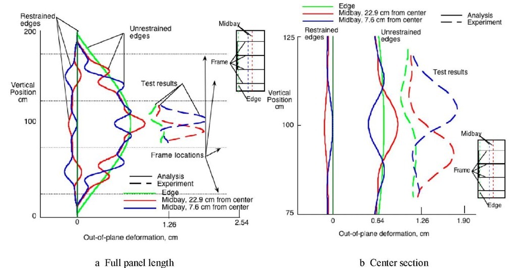
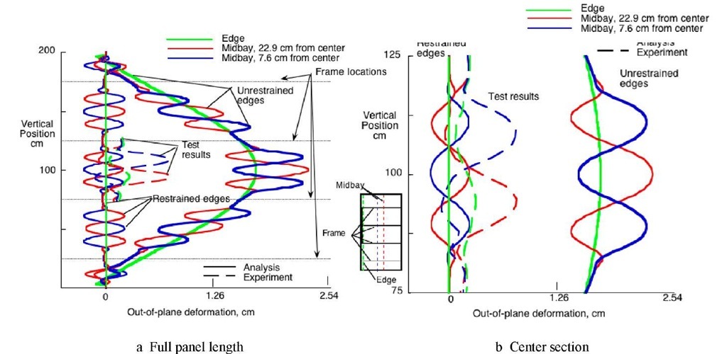
Out-of-plane deformations at a load level just prior to failure along the left edge, midbay location nearest the center of the panel, and midbay location one bay away from the center are shown in figure 12 for the thick-skinned panel and figure13 for the thin-skinned panel. The analytical results show the full panel length and are represented by solid lines, while test results were only obtained between two center frames and are shown as dashed lines. The edge is shown in green and the midbay locations are shown in red and blue. Frame locations are indicated by light black dashed lines. These results show that the edges and frame locations again deform out-of-plane. Test results show that in the thick-skinned panel, one edge of the panel moved out-of-plane by approximately 1.2 cm, shown in figure 12b, while the thin-skinned panel moved out-of-plane approximately 0.20 cm, shown in figure 13b. The thick-skinned panel failed at a load of 918.6 kN while the thin-skinned panel failed at a load of 889.6 kN. The modifications to the support structure reduced the out-of-plane motion for approximately the same load level and allowed the thin-skinned panel to support almost as much load as the thick-skinned panel. Both panels display local buckling between the stiffeners. Notice that the edge in both unrestrained edge cases shows a global single half-wave deformation shape along the panel length, while the midbay locations show local deformations between the frames superposed on the global shape. Buckling mode shapes of several half-waves occur between the stiffeners and add to the global deformation. In the thick-skinned panel, the test data indicates a larger amplitude of the global buckle than either of the analysis cases, and local buckle amplitudes which are approximately the same as seen in the unrestrained edge case. In the thin-skinned panel the test results show little global deformation and local buckle amplitudes which are close to what is predicted for the unrestrained edge case.
Fig 12 Out-of-plane deformation of thick-skinned rod-stiffened panel at a load of approximately the failure load.
Fig 13 Out-of-plane deformation of thin-skinned rod-stiffened panel at a load of approximately the failure load.
The out-of-plane motion of the unstiffened side of the rod-stiffened panels resulting from the assumptions of the restrained and unrestrained unloaded edges are shown in figures 14 and 15. Analytical result for the thick-skinned rod-stiffened panel for the restrained and unrestrained conditions at a load of 890 kN are shown in figure 14a and 14b, respectively. Analytical result for thin-skinned panel with restrained edges at a load of 934 kN is shown in figure 15a. Analytical result for thin-skinned panel with unrestrained edges at a load of 778 kN is shown in figure 15b. The deformation patterns are similar but not identical to the test data shown in figure 11. The thick-skinned and thin-skinned rod-stiffened panels support 70 and 97 percent of their Design Ultimate Loads, respectively. The lack of adequate edge restraints appears to have contributed to the premature failure.
For all three panels, the VIC system was critical to understanding the effect of the restraint system. Test results indicated that the restraint system for the hat-stiffened panel did not fully constrain the panel as intended. However, the panel design limited the global buckling and allowed local buckling to occur. The global buckling was not significant enough to prevent the panel from meeting its design requirements. The restraint system for the thick-skinned rod-stiffened panel did not fully constrain the panel as intended, which led to global buckling and premature failure. The modified restraint system for the thin-skinned allowed small deformations at the restraint points, however the panel displayed the expected local buckling and supported 97 percent of its design load.
Fig 14 Analytical predictions of out-of-plane deformation the thick-skinned rod-stiffened panels at a load of approximately failure load.
Fig 15 Analytical predictions of out-of-plane deformation the thin-skinned rod-stiffened panels at a load of approximately failure load.
CONCLUDING REMARKS
Three composite panels were loaded to buckling and failure in axial compression. In each case, the panel deformation was a combination of a global one-half wave deformation shape and a local multi-wave shape between stiffeners. The amplitude of the global wave was dependent upon the edge restraint system. Both test and analyses indicate that the restraint system did not fully restrain the edges of the panels during testing. Without the measurements at the panel edges provided by the full field measurement system, the edge behavior would not have been quantified. An improved restraint system was used for the thin-skinned rod-stiffened panel because, by the time of that test, it was understood that the prior restraint systems were not limiting out-of-plane motion as well as had been assumed. This understanding of the limitations of the restraint system relied upon the data provided by the full-field measurement system.


