ABSTRACT
When a panel is tested in uniaxial compression in a test machine, the boundary conditions are not quite the same as they would be if it were part of a complete structure. A restraint system may be used to simulate conditions found in a complete vehicle. Quantifying the quality of the restraint with only point-measurement devices can leave an inadequate characterization of the out-of-plane behavior. However, today’s full-field displacement monitoring techniques allow for much more accurate views of the global panel deformation and strain, and therefore allow for a better understanding of panel behavior. In the current: study, the behav ior of a hat-stiffened and two rod-stiffened carbon-epoxy panels is considered. Panels were approximately 2 meters tall and 0.76 to 1.06 m wide. Unloaded edges were supported by knife edges and stiffeners were attached to a support structure at selected locations to restrain out-of-plane motion. A comparison is made between test results based on full-field measurements and analyses based on assumptions of boundary conditions of a completely rigid edge restraint and the absence of any edge restraint. Results indicate that motion at the restrained edges must be considered to obtain accurate test-analysis correlation.
INTRODUCTION
When a panel is tested in uniaxial compression in a test machine, the boundary conditions are not quite the same as they would be if it were part of an entire wing or fuselage structure. The panel is usually supported by a restraint system which may be representative of the support found in an aircraft structure. Quantifying the quality of the restraint with only point-measurement devices can leave an inadequate characterization of the out-of-plane behavior. However, today’s full-field displacement monitoring techniques allow for much more accurate views of the global and local panel deformation.
The ends of a composite compression panel are usually encased in a potting compound which is surrounded by a steel support to prevent end brooming. The unloaded edges are often supported by metallic knife edges to restrain the panel from deforming in a global single half-wave mode, and to prevent the free edge of a thin skin region from buckling into shorter wavelengths. Analytically, these supports are often approximated by restraining all degrees for freedom except axial shortening for the entire potted region, and restraining all out-of-plane motion along the unloaded edge. In addition, a restraint system is also often included to restrain the panel from out-of-plane motion. A support structure is attached to panel stiffeners, where the connection points are assumed to fully restrain out-of-plane motion but allow in-plane motion. The validity of these assumptions is considered in this paper for three carbon-epoxy panels. One hat-stiffened and two rod-stiffened panels loaded in axial compression are discussed herein. In this case, "hat-stiffened" refers to hat-stiffeners in the loading direction and "rod-stiffened" refers to stiffeners with pultruded carbon rods in the stiffeners in the loading direction. Each panel was fabricated by the Boeing Company and provided to NASA Langley Research Center for testing.
TEST ARTICLES AND ARRANGEMENT
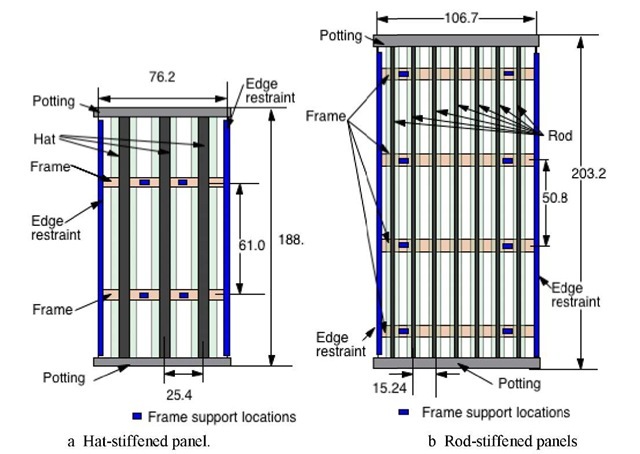
Each panel had stringers in the loading direction and frames perpendicular to the stringers, as shown in figure 1. The hat-stiffened panel was 1.885 m tall and 76.2 cm wide, and contained three hat-stringers and two blade-frames. The hat-stiffener spacing was 25.4 cm and the frame spacing was 61 cm. The rod-stiffened panels were 2.032 m tall and 1.067 m wide, and contained seven rod-stringers and four hat-frames. The stringer spacing was 15.24 cm and the frame spacing was 50.8 cm. The hat-stringers and hat-frames were supported by Rohacell foam on the inside of the hats. All three panels were fabricated from dry components that were infused with resin using high temperature and vacuum pressure. Skins, flanges, tear straps and webs were composed of layers of graphite material forms that were prekitted into multi-ply stacks using Hercules, Inc. AS4 fibers. Each nine-ply stack had a [45/-45/02/90/02/-45/45]T stacking sequence of approximately 0.132 cm thickness. Several stacks of the prekitted material were used to build up the desired thickness and configuration. Stringer and frame flanges were stitched to the skin using Vectran fibers; no mechanical fasteners were used for joining. Panels were infused with HexFlow VRM-34 epoxy resin using a VARTM process as described in reference 1.
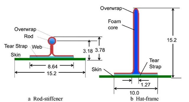
In the hat-stiffened panel, the skin and hats were composed of two stacks of material with a total approximate thickness of 0.264 cm. The blade-frames were composed of four stacks with a total approximate thickness of 0.528 cm. The hats and blades were 5.5 and 5.0 cm tall, respectively. Sketches of the hat stiffener and frame cross sections are shown in figures 2a and 2b, respectively. For both of the rod-stiffened panels, the sides of the hat frames and the stringer webs were each composed of two stacks with a total approximate thickness of 0.264 cm. The rod-stiffeners contained pultruded rods with a diameter of 0.95 cm which were surrounded by one stack of material. The rod-stiffeners were 3.78 cm tall and the frames were 15.2 cm tall. The skin of one rod-stiffened panel was one stack thick and the skin of the other was two stacks thick. These panels will be referred to herein as the thin-skinned and thick-skinned rod-stiffened panels, respectively. Sketches of the rod-stiffener and hat-frame cross sections are shown in figures 3a and 3b, respectively.
Each of the three panels considered in this study had potted loaded ends, metal edge restraints along the unloaded edges, and a steel support structure attached to the frames. The edge restraints and support structure were intended to prevent out-of-plane motion in the form of a single half-wave along the panel length. The edge restraints are shown in figure 1.
Fig 1 Panel geometry. Dimensions are in cm.
Fig 2 Stiffeners in hat-stiffened panel. Dimensions are in cm.
Fig 3 Stiffeners in rod-stiffened panels. Dimensions are in cm.
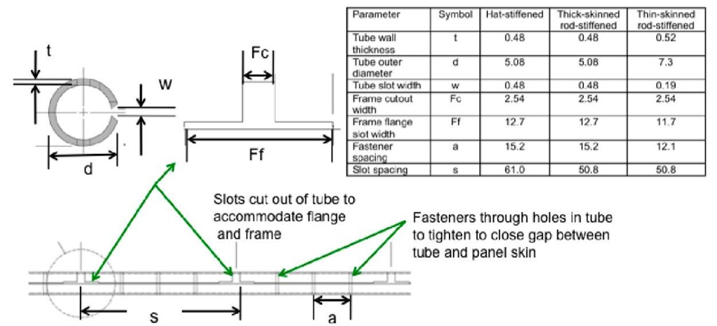
The dimensions of the steel tube edge restraints for the three panels are shown in figure 4. The steel tube was slightly shorter than the length of the panel between the potting to allow for axial shortening during the test. A slot was cut through the wall thickness for the full length of each tube so that the tube could slide over the panel skin. However, since the frames extended to the panel edges, cutouts in the tubes at each frame location were required to accommodate the frames. The edge restraints were required to just touch the surface of the panel. Small fasteners were inserted through holes in the tubes so the fasteners could be used to close the slot to match the skin thickness after the tube was in position. Teflon tape was placed between the panel surface and the restraint so that the panel would not bind up on the restraint during shortening. The edge restraints for the thick-skinned rod-stiffened panel was the same as for the hat-stiffened panel except for the different spacing for the cutouts for the frames, as indicated in the figure. The tubes for the thin-skinned rod-stiffened panel had a larger diameter and wall thickness than for the other two panels.
Fig 4 Edge restraints with dimensions in cm.
Additionally, since the frames would not be totally free to move in a real structure, a support structure was used on all panels to prevent out-of-plane motion at two locations on each frame, as shown in figure 5. Steel channel arms were attached to clips on the frames and the arms were attached to uprights behind the panel. The uprights were attached to a steel I-beam sitting on the floor. These arms were pinned to the clips and to the uprights so the restraints did not restrict rotation of the frames during loading, as shown in the close-up in figure 5d. However, the frame support structure was not attached to the floor or test machine during loading for the hat-stiffened or thick-skinned rod-stiffened panel. The floor I-beam was attached to the floor and angle bars were attached between the frame support and the floor during the test of the thin-skinned rod-stiffened panel as shown in figure 5c. In addition, lateral supports connecting the midlength position of the edge supports to the frame support assembly were added for the thin-skinned panel test to ensure that the tubes could not move out-of-plane during loading. These features are noted in figure 5c. Shims were also added to take up tolerances where the arms were pinned to the uprights in the frame restraint system.
Fig 5 Panels in test machine
INSTRUMENTATION AND TEST PROCEDURE
Each panel was monitored during loading using approximately 80 strain gages, 8 LVDTs and a full-field optical measurement system. The optical measurement or Vision Image Correlation (VIC) system [2] was used to obtain full field displacement and strain results for the unstiffened side of the panel skin during the loading of each specimen. The VIC system required a black and white speckle pattern be painted on the specimen surface, and used two cameras positioned at different angles to the specimen surface to simultaneously photograph the specimen at set intervals during the test. In these tests, the specimen was photographed every 2 to 5 seconds, resulting in approximately 150 time steps of data. The VIC system also recorded the load from the test machine so images could be related to the corresponding load. The VIC system compared the photographic images and produces three-dimensional displacements and strains. For each panel, the section between the centermost frames was monitored using the VIC system. A typical VIC arrangement is shown in figure 6.
Photographs of the hat-stiffened, thick-skinned and thin-skinned rod-stiffened panels in the test machine are shown in figures 5a, 5b and 5c, respectively. The stiffened surface was painted white to improve the video images and was not monitored using VIC since restraints, instrumentation and shadows would limit the clear vision area of a VIC image.
Each panel was loaded in a series of tests at a load rate of between 100 and 200 kN/min. Even though each panel was subjected to barely-visible impact damage prior to loading, these impacts did not significantly affect the panel behavior and are not visible in the VIC data, so this damage is not considered in the current paper.


