ABSTRACT
Nano-engineered intermetallic composites have been recently developed and identified as an emerging technology for a number of breakthrough downhole applications at Baker Hughes. This type of intermetallic composite is composed of particulate metallic phases with specifically designed intermetallic intergranular interphases, which may behave very differently from conventional metal-based composites and alloys. The customized design of these materials yields unique mechanical and chemical properties preferred for various downhole applications.
To characterize the shear properties of the material that often needs special attention, a proven shear test method, the V-notched beam or Iosipescu shear test method (ASTM D5379), was used for the targeted materials. However, when this test method was applied to the selected intermetallic composite, complicated off-axial two-path fractures, rather than a desired pure shear failure mode, were observed. To investigate the failure mechanism and the effectiveness of the ASTM testing method, a full 3-D finite element model was created and investigated using an extended finite element method (XFEM). Based on the finite element analysis results and the additional shear tests of a reference alloy with similar base metal composition, the true material system-dependent failure mechanisms were identified and the test method was further validated. A special mechanical design guideline for this innovative nano-engineered intermetallic composite material was also recommended.
KEYWORDS
Intermetallic Composites, V-notched Beam or Iosipescu Shear Test Method, Failure Mechanisms, XFEM, Crack Initiation and Propagation
INTRODUCTION
A variety of service tools and critical components such as removable or drillable tools used in oilfield downhole operations require only a temporary setting or a limited lifetime in the wellbores. After the services are completed, these tools or components need to be removed or dispersed from the wellbores to recover fluid paths for hydrocarbon production. The conventional removal technologies such as retrieving, drilling or milling operations require additional trips into the deep well. These steps usually involve various intervention tools and heavy surface equipment. These operations are usually time consuming and very expensive.
Furthermore, in hydraulic fracturing operations, a series of molded plastic or fiber-reinforced plastic tripping balls with varied sizes is commonly used as flow and pressure control means for fracturing operations. After the fracturing treatment for the formation, the frac balls are intended to be flowed back to the surface with well fluids. Frac ball technology has been commonly used in fracturing operations, but there is still a big concern about limitations of strength, stiffness and operating temperature of the currently used frac balls as well as the ball flow-back uncertainty.
An ideal solution for such service tools and components is to have a specially designed "smart" material that would have high mechanical strength in the initial operating state, but with the ability to degrade or dissolve after a certain period of exposure to wellbore conditions. This will eliminate all the expensive interventional operations and the concerns and uncertainty in current hydraulic fracturing operations.
To solve this problem, a series of nano-engineered intermetallic composite materials (ICM) with high mechanical strength and stiffness and a controlled dissolution rate was developed to provide such smart performance for various critical downhole applications. The ICM is commonly composed of particulate metallic phases with specifically designed intermetallic intergranular interphases. Due to the special material design, this material may behave very differently from the conventional metal-based composites and alloys. In order to understand the mechanical behavior of the material better and use it in various downhole applications, detailed mechanical and chemical properties must be characterized to provided design guidelines. In this paper, the shear mechanical properties of the intermetallic composite material are investigated using the V-notched beam method.
The V-notched beam or Iosipescu shear test method was first proposed by N. Iosipescu in 1967 [1] and became ASTM standard shear test method D5379 for composite materials in 1995 [2,3]. This test method has been known as a proven shear test method and used extensively for composite and other material systems because a nearly uniform pure shear stress state is presented in the notched gage section of the test specimen under a shear load. However, when this test method was applied to a selected intermetallic composite material, complicated off-axial two-path fractures, rather than a desired pure shear failure, were observed.
This observation may suggest two possible mechanisms for such an undesirable failure mode: (1) improper geometry of the test specimen or test method resulted in a different failure mode, or (2) special inherent material behavior of the new intermetallic composite imposed the change in the failure mode. To investigate the failure mechanism behind the undesirable failure mode and to further evaluate the V-notched beam test specimen design, a 3-D finite element model was created using Abaqus™ advanced modeling technique, the extended finite element method (XFEM). By using the XFEM technology, crack initiation and propagation was investigated for different specimen designs. Also, additional V-notched beam shear tests were further conducted with the same test specimen geometry for a reference metal alloy with similar base metal composition. Based on the finite element analysis and additional shear test results, the true material system-dependent failure mechanisms were identified and the test method was further validated.
EXPERIMENTAL
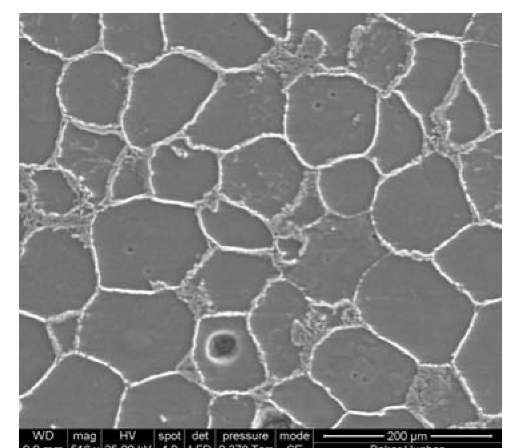
Material: The material under investigation is a specially designed intermetallic composite material (referred as Baker ICM hereon). It is composed of the particulate metal phases and the intermetallic intergranular phases as shown in Figure 1. The nano-engineered intergranular interphases are designed to achieve preferred mechanical and chemical properties. The overall intermetallic composite properties are then governed by both the particulate metal phases and the intermetallic intergranular interphases.
Fig. 1 SEM micrograph showing typical microstructure of the Baker ICM with metallic particulate phases and the intermetallic intergranular interphases.
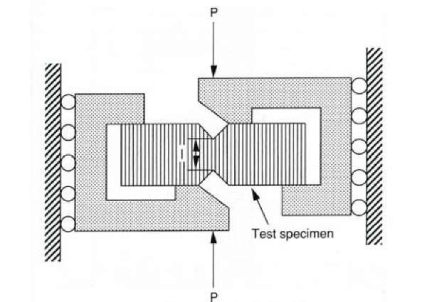
Fig. 2 Schematic of loading fixture for the V-notched beam shear test.
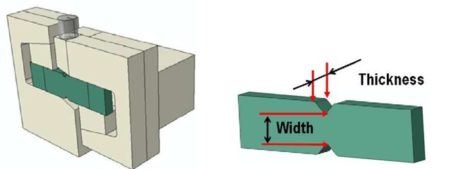
V-Notched Beam Shear Test: The shear test method used in this study is the ASTM standard test method D5379, the V-Notched Beam Method [3]. In this shear test method, a standard V-notched beam test specimen is mounted at two end sections in a specially designed test fixture as shown in Figure 2. Under shear loading, a nearly uniform shear stress is generated in the center plane of the notched gage section of the specimen as illustrated in the literature [3].
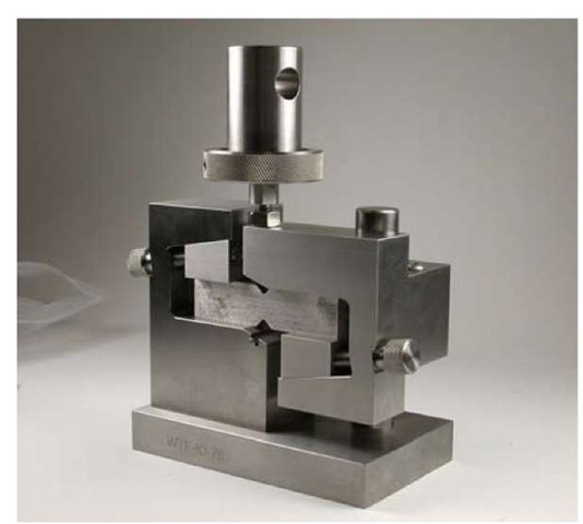
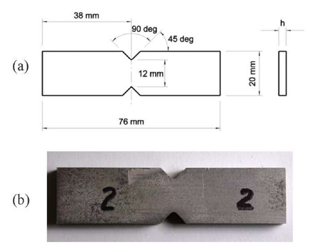
The standard test fixture used in this study was provided by Wyoming Test Fixture (WTF) Inc. A photograph of this test fixture with a test specimen installed in place is presented in Figure 3. The geometry of a standard V-notched beam test specimen is illustrated in a sketch shown in Figure 4a and a wire-EDM machined V-notched beam test specimen of Baker ICM is shown in Figure 4b.
The shear tests were conducted using a servo hydraulic MTS test frame equipped with a 10 kip load cell. To apply shear load, the actuator is moved at 2 mm/min under displacement control mode until fracture of the test specimen occurs. A digital video camera is set to capture the fracture process for supplemental information. For comparison, additional V-notched beam shear tests were also conducted for a reference standard metal alloy with similar base metal composition as in the ICM, and referred as Base Alloy hereon.
Fig. 3 ASTM D5379 standard test fixture with a standard V-notched beam shear test specimen installed.
Fig. 4 (a) Standard geometry of a D5379 V-notched beam test specimen and (b) a machined standard test specimen of Baker ICM.
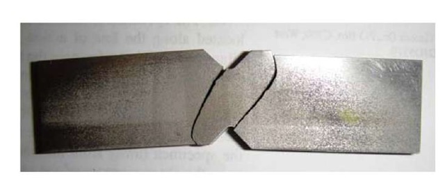
Fig. 5 V-notched beam specimen of Baker ICM failed in an off-axial two-path fracture under shear loading.
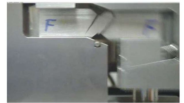
Fig. 6 Digital camera video picture caught the crack propagation direction in the Baker ICM beam specimen in the test fixture during the shear test.
Test Results and Discussion: Three V-notched beam shear tests were conducted on the MTS test frame using the WTF D5379 standard test fixture as described previously. Rather than a desired pure shear failure across the notched gage section, all the test specimens were actually fractured in an off-axial two-path mode as shown in
Figure 5. The shearing process was not recorded using a true high-speed camera, but the video recorded was enough to identify the crack propagation direction as shown in Figure 6.
From the observed fracture pattern of the broken specimen as well as the recorded video, it is concluded that the crack was initiated at the upper or lower notch surfaces near the roots of the notches and then propagated along the direction nearly 45° from the principal axis. For comparative purpose, four additional standard V-notched beam test specimens of the Base Alloy were prepared and tested under the same testing procedure, at the same displacement speed and using the same test fixture per ASTM D5379. With all the Base Alloy specimens, the desired true shear failure mode across the notched sections was indeed observed as shown in Figure 7.
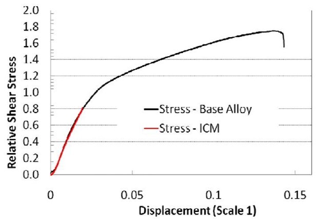
To make the test data more intuitive in comparison without exposure of the company’s proprietary technical information, the stress data of the Baker ICM and the Base Alloy were normalized by the critical shear yield strength of the Base Alloy. Typical normalized average shear stress across the center plane of the notched cross section versus displacement curves from both the Baker ICM and the Base Alloy specimens are plotted in Figure 8, respectively. The normalized mechanical properties of the Base Alloy and the Baker ICM are presented in Table 1 based on our test results and manufacturer published data.
Fig. 7 V-notched beam specimen of base alloy failed in a true shear failure mode under shear loading.
Fig. 8 Normalized average shear stress across the notched cross section versus displacement curves for Baker ICM and the Base Alloy specimens.
Table 1. Comparison of Mechanical Properties of Baker ICM with Base Alloy (Stress data are normalized by the shear yield strength of the Base Alloy)
|
Tensile Strength |
Tensile Yield Strength |
Shear Stress at failure |
Shear yield Strength |
Tensile Modulus initial |
Tensile Elongation |
|
|
Base Alloy |
3.06 |
2.59 |
1.75 |
1.0 |
1.00 |
1.00 |
|
Baker ICM |
2.12 |
1.62 |
0.82 |
- |
1.09 |
0.22 |
From the normalized average shear stress versus displacement curves presented in Figure 8 and the normalized test results presented in Table 1, we can see that the average shear stress of the Base Alloy specimen was running through its yield point and reached its ultimate shear stress at a normalized value of 1.75. This corresponds to an ultimate shear strength of the alloy that is within the range of the manufacturer published values for the alloy.
In contrast, the average maximum shear stress in the notched gage section of the Baker ICM specimen is found to be only at a normalized value of 0.82, with an off-axial two-path fracture mode indicating an unacceptable premature failure of the Baker ICM specimen before reaching its shear yield point. To understand this undesired failure mode and failure process, it is important to uncover the failure mechanisms behind them. The following are some our considerations on the possible failure mechanisms.
It is noted that when the V-notched beam specimen is under shear loading in the standard test fixture, a nearly uniform pure shear stress is generated in the center plane of the notched gage-section. The shear stress direction is parallel to the shear loading direction or the vertical direction. While the pure shear stress is distributed in the center plane, the principal stresses in tension and compression are also distributed and applied to the gage section of the specimen in the direction of ±45° correspondingly. Beside this, bending moments at the off-the-center-plane locations also generate certain tensile stresses in the notched sectional area.
It is also noted from Table 1 that the tensile yield strength and the ultimate tensile strength of the Baker ICM are relatively low. When the maximum principal tensile stress along the 45° direction in the notched section of the specimen reaches or approaches the tensile strength of the material, a small crack may be initiated at that location, especially in the brittle interphase areas. The crack may propagate thereafter before the shear stress in the notched gage section reaches its failure level. In contrast, the Base Alloy shows more ductile feature with much higher tensile yield strength and ultimate tensile strength. Therefore, the tensile-failure induced off-axial fracture does not occur when the shear stress reaches its shear strength. These result in a true shear failure mode in the notched Base Alloy specimen. To fully and clearly understand the fracture mechanism of the Baker ICM material and further validate the V-notched beam test method, a series of finite element analyses were performed.
FINITE ELEMENT ANALYSIS OF V-NOTCHED BEAM TEST
XFEM Model and Material Modeling: Due to the complexity of the shearing process, a 3D finite element model was used to fully investigate the fracture mechanism. Because of the difficulty in predicting the failure mode in the notched Baker ICM test specimen and how the crack will initiate and propagate, it is preferable to use a simulation technology that does not require a pre-defined crack path. The newly developed Abaqus 6.10 software [4] is equipped with an advanced new feature, the extended finite element method (XFEM). It uses enriched features to handle crack initiation and propagation automatically, based on the pre-defined material properties including fracture toughness. XFEM technology is a perfect tool to simulate crack initiation and propagation for the Baker ICM notched beam shear test.
Figure 9 shows the established 3D model based on the standard notched beam shear test method. During the simulation, the notched section width of the specimen is of interest, and investigation of failure mode versus different widths was conducted. With XFEM, the first-order brick and tetrahedron elements are required. Since our target is the specimen, enriched feature is only applied to the specimen. As for the material properties, they were obtained from previous experiments, and the fracture toughness was estimated based on the mechanical test results.
Fig. 9 Full 3D model and specimen designation
XFEM Results and Discussion: Detailed finite element analyses were conducted for the specimens with five different notched-section widths, specifically 50%, 75%, 100% and 120% of the standard width, and one additional without a notch. The standard specimen with 100% of the standard width was first investigated as a benchmark to check the fidelity of the simulation.
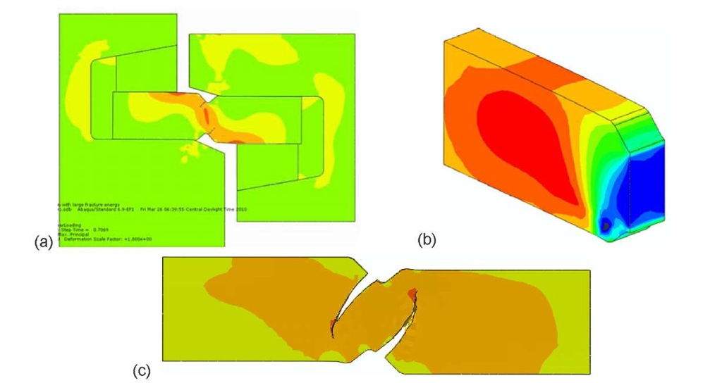
Figure 10a and 10c show crack initiation at the notch surface near the root and crack propagation through the specimen in nearly 45o off axial directions, respectively, based on the analysis defined in the maximum principal stress field. As shown in these two figures, the simulated fracture mechanics process matches closely with the experimental result as shown in the photo presented in Figure 5. This confirmed our considerations on fracture mechanisms for the Baker ICM specimens in the tests.
With the fracture process matching closely the experimental results, it is reasonable to correlate the shear stress from the simulation. It is thus noticed that the corresponding pure shear stress distribution in the center plane of the notched gage-section is as expected, nearly uniform, as shown in Figure 10(b).
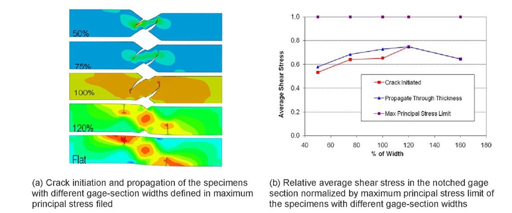
As soon as the fidelity of the model was verified, we wanted to know how the notched section width of specimen would affect the fracture mode. In other words, was it possible to obtain true shear failure for this type of material? Figure 11a shows crack initiation and propagation for all five different geometry configurations defined in the maximum principal stress field. As the width gets smaller, the only difference is that the calculated average shear stress at fracture is getting smaller, but the fracture pattern remains the same. This corrected some of our initial thinking of forcing the specimen to be fractured in shear mode by reducing the width of the specimen’s notched section. Figure 11b shows the calculated average shear stresses in the notched gage section of the specimens with different gage-section widths, normalized by the maximum principal stress limit. It shows that for the standard specimen, the average shear stress reaches almost the maximum value. This partially demonstrates the standard V-notched specimen design is at its optimized geometry.
(a) Crack initiation during shear loading defined in maximum principal stress field; (b) Shear stress distribution in the center plane of the notched gage section; (c) Crack propagated to closely match the experimental results defined in maximum principal stress field.
Fig. 10 XFEM results for standard specimen geometry.
Fig. 11 FEA results for five specimen geometry configurations.
CONCLUSIONS AND RECOMMENDATION
Based on the experimental results of the V-notched beam shear tests from both the Baker ICM and the Base Alloy and the XFEM analysis results for the V-notched beam test, it is concluded that:
1. The V-notched Baker ICM shear specimens under shear loading failed in an off-axial two-path fracture mode rather than a desired pure shear failure mode in the plane between the two notches. Finite element analysis results indicate the off-axial fracture was initiated from a maximum principal stress-induced tensile failure near the root of the notches and propagated along the principal stress direction even after reducing the notched section width. However, using the same test method for the Base Alloy test specimens, a true shear failure mode was obtained.
2. The V-notched beam shear test method, in general, is a valid shear test method and the geometry of the standard V-notched beam test specimen is in optimized condition because a nearly uniform pure shear stress state is generated in its notched gage section under a shear load. Since this test method could not generate a true shear failure mode with the current Baker ICM material, we recommend not using this test method for determining its shear strength. However, this test method is still a valid method for shear modulus determination of this ICM material and for shear property determination of other materials so long as it can generate a true shear failure mode.
3. In component design and analysis with the current Baker ICM material, if the major loading condition involves shear, it is recommended to consider examining the maximum principal stresses and identifying possible tensile failure based on the measured tensile properties of the material.
