Abstract
Vehicle heating, ventilating, and air-conditioning (HVAC) systems are necessary standard equipment in today’s manufactured vehicles. These systems not only provide comfort to the cab crew, but also are an important safety feature that ensures a demisted cab environment and that can defog the windows in all kinds of weather. This entry provides the reader a short synopsis of mobile HVAC systems, including each component’s operation as well as the configurations of current and future systems.
NOMENCLATURE
Effective temperature a combination of relative humidity and temperature, which can indicate the level of comfort perceived by the human body.
Operator/passenger/patient (further—operator) enclosure part of the machine that surrounds the operator, preventing the free passage of external air, dust, or other substances into the area around the operator. This surround shall comprise components such as glass, roof, and floor.
Operator environment the space surrounding the operator, as defined by temperature and velocity measurement.
Air-conditioning (AC) system any system that lowers the effective temperature of the air within the operator enclosure.
Heating system any system that raises the effective temperature of the air within the operator environment.
Ventilate air change for comfort in the area around the operator in an operator enclosure.
Ventilating system any system that provides fresh air to and maintains air circulation within the operator enclosure.
Outside air/fresh air the unconditioned air entering the operator enclosure.
Recirculated air the air within the operator enclosure that passes through the AC system.
Recirc mode the HVAC unit operational mode uses 100% recirculated air.
Cooling decrease of the temperature of the air inside the operator enclosure.
Heating increase of the temperature of the air inside the operator enclosure.
Pressurization pressure differential between the static pressure inside and outside the operator enclosure.
Pressurization system means used to pressurize the operator enclosure, including any components that influence the performance of the system.
Filtration removal of dirt and dust particles from the air forced or drawn into the operator enclosure by mechanical means.
Filtration system means of removing dirt and dust from the air entering the operator enclosure.
Filter efficiency measure of the capability of the air filter element to remove particulate matter.
Solar heating heating factor from the sun to be considered in determining air-circulation and cooling requirements necessary to maintain a comfortable temperature inside the operator enclosure. Solar heating must be considered carefully when designing the system. Solar radiant energy causes a heating effect to be considered in determining cooling capacity and insulating requirements. Also, direct radiation on the operator can cause discomfort not easily overcome by the system.
Solar radiant energy process by which solar heating is generated.
Ambient temperature the air temperature at which the equipment will normally operate is one of the most significant factors to be considered in determining the capacity required for proper heating or cooling of the operator enclosure.
Mechanical load heat transferred to the operator enclosure from the engine, transmission, hydraulics, etc. This load must be considered when locating system components, and it may require special insulation.
Dirt and dust must be considered when designing the filtration system and when locating components, particularly those outside the operator enclosure.
Global factors ambient conditions of the various markets that the vehicle will operate in. (Compare North America with Europe for ambient loads.)
Heat transfer transfer of heat from liquid to air; this heat is directly proportional to the difference between the temperatures of the liquid and air entering the transfer system for a given rate of liquid flow and airflow measured in kg/s or kg/hr and that heat removed from liquid is equal to the heat given to air.
Heating/defrosting system the system used to heat the cab interior and to clear the windshield, including all ducting, fans, and heat-exchanger equipment. This system is the means intended to defrost the windshield and specified portions of the right and left windows.
Defrosting melting frost on the inside of the glass, or on the test coating on the outside surface of the glass, with the defroster/demister system.
Defrosted area the area of the windshield and the right and left windows composed of dry, cleared surface and melted or partially melted (wet) test coating, excluding that area of the windshield covered with dry test coating.
Coolant liquid used for heat transfer, composed of 50% ethylene glycol and 50% water or other liquids specified by the vehicle manufacturer for use in the heat transfer system.
Heat-exchanger system provides heating and windshield defrosting and defogging capabilities in a vehicle. The system consists of an integral assembly or assemblies, with a core assembly or assemblies, blower(s), fan(s), and necessary duct systems and controls to provide heating, defrosting, and defogging functions.
Heat exchanger core assembly in general, the core consists of a liquid-to-air heat transfer sur-face(s), liquid inlet, and discharge tubes or pipes.
Evaporator assembly a coil (heat transfer surface) that forces air over the heat transfer surface into the cab and the complete enclosure (AC unit) to be furnished for the installation.
Heat exchanger/defroster duct system passages that conduct inlet and discharge air throughout the heat exchanger system. The discharge outlet louvers are part of the system.
Air delivery rate the actual rate of airflow (standard air volume flow rate as specified in “System Components and Duties”) for wet coil conditions.
Cooling capacity (air side) the amount of heat absorbed from the air flowing through the evaporator (W and kW).
Cooling capacity (refrigerant side) the amount of heat absorbed by refrigerant flowing through the evaporator tubes (W and kW).
Dry-bulb temperature air temperature in °C (K) as read from a standard thermometer or other appropriate temperature-measuring device.
Wet-bulb temperature air temperature in °C (K), essentially equal to that read from a wet-bulb thermometer or one whose sensing bulb is covered by a water-wetted wick located in the moving ai stream.
Relative humidity ratio of the amount of moisture (in mol-fraction) present in the air to the maximum amount the air can hold at the same temperature and pressure.
Humidity ratio ratio of the mass of water vapor to the mass of dry air (kgw/kga).
Dew point (saturation) temperature air temperature in °C (K) at which moisture begins to condense out as the air is cooled at constant pressure.
Specific volume ratio of the total volume of moist air to the mass of dry air (m3/kga).
Specific heat the amount of heat required to raise the temperature of a kilogram of a substance (air, liquid, etc.) by 1 K. Specific heat is a function of temperature. Cpa= Specific heat of the air in J/(kga • K).
Specific gravity of liquids ratio of the mass of liquid to the total volume of liquid at a certain temperature (kg/l).
Enthalpy (sometimes total heat) a convenient energy concept defined from the properties of a system. Enthalpy describes how much heat a substance contains, determined from a predetermined base or starting point. Often, enthalpy refers to the total heat (not very accurate statement) content (sensible and latent) present in the air (J/kga) equal to the sum of the individual partial enthalpies of the dry air and water vapor.
Sensible heat the amount of heat associated with a change in the dry-bulb temperature of the air.
Latent heat the amount of heat required to change the state of a substance. Specifically, it is the heat released as water vapor condenses out of moist air and also the heat associated with the phase change of certain heat transfer fluids (volatile refrigerants, steam, etc.).
Entropy a microphysical property of thermo
dynamic systems. It is completely transferred from one system to other during a reversible process, whereas it always increases during an irreversible process in a closed system.
Discharge line high-pressure (inlet) line that carries liquid refrigerant to the expansion device.
Suction line low-pressure (outlet) line that carries evaporated (gaseous) refrigerant to the compressor.
Subcooling the degrees of temperature below saturation (based on the inlet pressure of the
expansion device) of the liquid refrigerant (°C or K).
Superheat the degrees of temperature above the saturation temperature (based on the outlet pressure of the evaporator) of the vaporized refrigerant (°C or K).
Expansion device a valve or fixed orifice in the refrigerant circuit with the purpose of metering refrigerant into the evaporator, inducing a large pressure drop and causing a change of state.
Compressor a device that pumps low-pressure refrigerant vapor out of the evaporator by suction, raises its pressure, and then pumps it under high pressure into the condenser.
Condenser a device that removes heat from the entering high-pressure, high-temperature, desu-perheated refrigerant vapor, changing it to a high-pressure, high-temperature liquid.
Evaporator a device that removes unwanted heat from the air by boiling liquid refrigerant in the evaporator coil.
Psychrometric chart a graphical presentation of moist-air properties.
Sleeper cab the occupant space behind the truck cab intended to be used as living space during travel or while the vehicle is parked.
Calorimeter a test fixture including a specially built air tunnel that directs all the air from the discharge face of the evaporator, heater, or condenser (or complete HVAC unit). The sampling device is set up at the end of the tunnel. The calorimeter is equipped with an AC and heating loop to simulate the HVAC system operations. Most of heat transfer parameters denominations correspond to reference.[1]
INTRODUCTION
An HVAC system is standard equipment for most of today’s manufactured vehicles. The mobile HVAC system’s main duty is to provide driver and passenger temperature comfort and to provide the required cab dehumidification during hot, high-humidity weather without failure due to device cooling capability, all while still allowing safe vehicle operation. It must cool down the vehicle enclosure within a short time, often within 30 min, at ambient temperatures up to 45°C-50°C. The dehumidification feature in great part determines the required system’s (evaporator’s) cooling capacity. The heating part of a mobile HVAC system should provide acceptable defrost, demist, and defog performance, yet the heater must make driver and passengers comfortable within a relatively short period after a cold startup in temperatures like — 30°C and lower (as in some cold areas of the United States or the world). The system must be quiet, and the controls must be easy to understand and operate.
This entry focuses on an overview of mobile HVAC system, including descriptions of each component. Also, in the entry “Mobile HVAC Systems: Fundamentals, Design and Innovations” of this topic will be provided the explanation of methods and approaches to system and components testing, capacity calculation, and design. At the end of that entry, prospective systems that take into account environmental impact and current no-idle regulations are presented.
HISTORY
The thermodynamic basis for modern AC began when the French military engineer Sadi Carnot (1796-1832) formulated the basic principles of the reversed Carnot Cycle. The aim of all clockwise-operating cycle processes is to produce work by transferring heat from a high-temperature energy reservoir to a low-temperature energy reservoir according to the first law of thermodynamics. The maximum amount of heat converted to work is determined by the second law of thermodynamics. Whereas the clockwise Carnot Cycle produces work, a reversed Carnot Cycle (operating counterclockwise) acts as a heat pump, requiring work to transfer heat from a low-temperature energy reservoir. The basic principles of a reversed cycle are explained by Sadi Carnot in his paper Reflections on the Motive Power of Fire.
The reversing Carnot Cycle that uses heat supplied as an energy source and delivers mechanical work as the energy output, one will get reversed engine which applies mechanical work that is supplying as the energy source to transfer heat from a lower energy reservoir to a higher energy reservoir. The latter statement is the basis for refrigeration and AC.
Today, nearly all on- and off-highway vehicles manufactured in and for the United States, as well as a significant number of other world vehicles, have AC as standard equipment: passenger cars, trucks, buses, farm and construction equipment, and specialty vehicles, among others. Today, a vehicle without AC is similar to a passenger car without a heater during the early 1930s, when heaters were still just options.
The first mobile AC systems were introduced in the late 1930s by Packard, Chrysler, and Cadillac. The first supplier was Bishop & Babcock Company of Cleveland, Ohio. In the mid-1940s, AC units appeared in the aftermarket in the Southwestern United States and were installed by dealers in small shops. The first plant installing AC units opened in 1953. This was the first and only unit in which an evaporator in a passenger vehicle was located in the trunk and ducted from there to blow air forward. In 1954, the front units were brought to the market by Nash and Pontiac. Today, all passenger vehicles have an HVAC system located in the front of the vehicle, but most buses, truck sleeper cabs, vans, and other vehicles are equipped with a rear HVAC system.
Over the years, the HVAC system has been greatly improved in the design of heat transfer surfaces, plumbing system, compressor, and air distribution. Today, the HVAC system is not only of important value to the vehicle, but also, very often it is necessary equipment (e.g., for ambulances and fire trucks). Standards in a large variety of industries include specifications and requirements for an HVAC system as a necessary option.
In the first AC systems, all plumbing was done by copper tubing connected by commercial refrigeration fittings. The compressor was four cylinder and camshaft operated. Those systems’ operational mode was 100% recirculation. A little later, fresh air/outside air capability was added to help improve the defrosting and demisting features significantly.
MOBILE HVAC BASICS: PHYSICS OF THE HVAC SYSTEM
The mobile HVAC system’s main duty is to provide driver and passenger temperature comfort and the required cab dehumidification during hot, high-humidity weather without failure due to device cooling capability and while still allowing safe vehicle operation. It must cool down the vehicle enclosure within a short time, often within 30 min, at ambient temperatures up to 45°C-50°C. The dehumidification feature in great part determines the required system’s (evaporator’s) cooling capacity. The heating part of a mobile HVAC system should provide acceptable defrost, demist, and defog performance, yet the heater must make drivers and passengers comfortable in relatively short periods after cold startups at temperatures of — 30°C or lower (in some cold areas of the United States or the world). The system must be quiet, and the controls must be easy to understand and operate.
HVAC systems have three fluid streams: air, coolant, and refrigerant. Each of these streams defines heat transfer between the corresponding heat exchanger and fluid. The automotive climate control system includes three main heat exchangers: the evaporator, condenser, and heater. An AC thermal system consists of the evaporator and condenser with two heat transfer fluid streams: refrigerant and air. A heating thermal system consists of the heater with two heat transfer streams as well: coolant and air. Each of these two thermal systems affects the human body’s comfort level in the summer or wintertime, correspondingly. Heat transfer processes in the thermal system are defined as exchanges of heat between the heat receiver (heat sink), which is refrigerant in an AC thermal system, and air in a heat thermal system and the heat supplier (heat source), which is air in an AC system and coolant in a heat system.
The physics of the evaporating and heating processes can be described as follows.
Evaporating Process
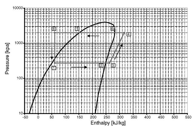
An evaporator acts as a device to lower the temperature of ambient or recirculated air that passes through it. The physics of the process is explained in the following manner: the low-temperature and low-pressure liquid refrigerant enters the liquid line of an evaporator, where it is boiled (evaporated) by the air coming through (evaporation Line 1-3 of the reversed Carnot Cycle; Fig. 1). The evaporator must provide stable refrigerant flow under every possible operating condition and should have sufficient capacity for rapidly lowering the vehicle’s cabin temperature.
Fig. 1 Pressure-enthalpy diagram HFC-134a.
The features of the evaporation process are based on the theoretical principles of the reversed Carnot Cycle (Fig. 1), which actually represents the ideal refrigeration cycle. From the features of this cycle immediately follow the necessary conditions for the best-performance evaporation process, which are constant pressure and temperature of the refrigerant on the evaporation line of the pressure-enthalpy diagram (Fig. 1). In view of this statement, it is clear that all other things being equal, the same evaporator provides more capacity when the refrigeration-process conditions are closer to the ideal refrigeration process (or reversed Carnot Cycle) conditions.
The next very important consideration that greatly affects the evaporator’s design is that the refrigerant’s circuiting must be designed to make the outer surface temperature as uniform as possible.
It is imperative to explain here the features of the refrigeration cycle (reversed Carnot Cycle) for better understanding of all HVAC parts’ assignments and duties. A compression-refrigeration cycle (Fig. 1) consists of the following phases: isentropic compression; condensation, including desuperheating, actual condensation, and sub-cooling; adiabatic expansion; and evaporation, including superheating (if any).
Compression (discharge Lines 3-4; Fig. 1) is accomplished by means of an AC compressor where superheated vapor enters the compressor at low pressure and temperature, and is compressed to a higher pressure and temperature. This task is performed at constant entropy in an isentropic process in which change in entropy is zero. The difference in enthalpy between the high-pressure and low-pressure gas is an amount of compressor work or a measure of available energy.
Condensation (Lines 4-6). The high-pressure superheated vapor is carried to the condenser, where the refrigerant undergoes the following three transformations (phases) utilizing outside ambient air: (1) the heat is removed from the gas refrigerant vapor to bring its temperature to a condensing point (desuperheating, Lines 4-4a); (2) gas is condensed to a liquid phase (actual condensation, Lines 4a-5), and (3) the liquid is subcooled to a specified level (subcooling, Lines 5-6). The difference between the enthalpy from desuperheating to subcooling is a measure of the heat content released to the ambient air.
The subcooled refrigerant liquid then undergoes expansion through an orifice device where it is expanded adiabatically (the change in enthalpy is zero; there is no heat exchange with surrounding), changing the phase to a low-temperature and low-pressure mixture of liquid and vapor gas (Lines 6-1).
The low-temperature and low-pressure mixture of liquid and vapor gas enters the evaporator, where the latent and sensible heat from the ambient or recirculated air passing through the evaporator core vaporizes (boils) the refrigerant into a gas phase (Lines 1-3). This process is performed at constant pressure and temperature. The difference in enthalpy between the liquid and gas refrigerant is a measure of the amount of heat removed from the air. This amount is defined by evaporator capacity. The evaporator also acts as a dehumidifier by condensing the water vapor (latent heat) from the air flowing through the coil. If the AC system is equipped with an expansion valve, either thermostatic (thermal expansion valve [TXV]) or electronic (electronic expansion valve [EXV]), the superheating line (Lines 2-3) continues the evaporation process. This system has to be equipped with receiver/dryer, located between the condenser and the expansion valve, where any moisture is removed from the refrigerant. If the AC system is an orifice tube (OT) system, the superheating line does not exist. The refrigerant exiting the evaporator has superheat equal to zero (a significant advantage of an OT system vs a TXV system). In an OT system, the entire evaporator surface is used to cool air, whereas in a TXV system, part of the evaporator surface is used to superheat gas (see the detailed comparison of TXV and OT systems in “System Configurations and Overview”). The OT system has to be supplied an accumulator located between the evaporator and compressor to prevent any liquid from entering the compressor.
The low-temperature and low-pressure refrigerant gas enters compressor through the suction line, and the cycle is repeated.
Heating Process
The heating process is less complicated than the evaporation process. The high-temperature liquid (usually, coolant from the engine’s cooling system) enters the heater core, where it is cooled by the air coming through. The heater must provide stable coolant flow under every possible operating condition. The heater core must be large enough to ensure the thermal comfort of the cab crew while the windshield is defrosted and the cab area is defogged within the requirements and conditions defined by the Society of Automotive Engineers (SAE). The above-mentioned consideration of uniformity of the surface temperature, which greatly affects the evaporator design, influences the selection of the heater core, which also must be designed to make the outer surface temperature as even as possible.
One more point that should be mentioned pertains to packaging constraints. Although it seems that these constraints are not so important, for the automotive application, packaging constraints end up being the most decisive factors in the design of the heat exchangers. Because the evaporator and heater are part of HVAC module, they should be packaged as part of the whole unit. Space is very limited; therefore, the selection of the heat exchanger type in great part depends upon space availability.
The same note has to be made with regard to the frontal area of the device. The frontal area should be separated from the whole apparatus because on one hand, the surface area is a very great factor in influencing the evaporator and heater capacity—that is, the greater this area, the better the heat exchanger’s performance. On the other hand, the frontal area of the heat exchanger is limited (again) by the space available for the device.
SYSTEM CONFIGURATIONS AND OVERVIEW
A mobile HVAC system consists of:
• H—heating system, which usually includes a heater core, a heater valve, controls, and plumbing
• V—ventilating part, which mostly contains an inlet cowl, ducts, a blower and blower housing, a blend air door (if any), mode doors, louvers, baffles, actuators, and a condenser fan with a fan shroud and seals
• AC—AC system that incorporates the condenser, evaporator, compressor, controls, expansion device, accumulator or receiver/dryer, and plumbing
The environment in which the vehicle operates sets the HVAC requirements. The heat load of the environment on the vehicle HVAC system consists of heat conduction into the crew/passenger compartment, air infiltration, heat pickup of the incoming air to the evaporator, sun load (more than 50% of total), driver’s and passengers’ body heat, and the heat (sensible and latent) of the incoming air. All the above-mentioned factors affect AC system performance. Similar considerations can be brought up with regard to the heating system’s performance, of course, bearing in mind the low ambient temperature that is required to warm the enclosure. Human-body and sun-load heat in an HVAC system’s heating mode help warm up the enclosure.
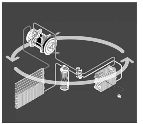
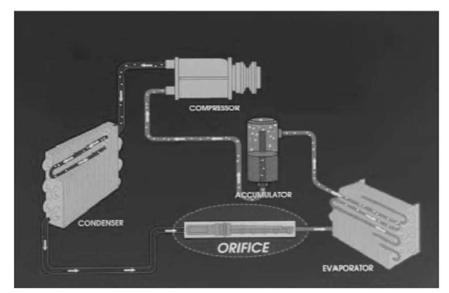
In Figs. 2 and 3, the TXV and OT mobile HVAC system schematics are presented. To familiarize readers with HVAC components and their operations, the following lists all these components.
• Compressor
• Condenser
• Receiver/dryer
• Expansion valve
• Orifice tube
• Accumulator
• Evaporator
• The supporting cast
How does an AC system work? As we have already discussed, we cannot create cold. The only means of reducing temperature is removing heat and maintaining enclosure temperature and humidity level. An AC system contain two sides: a high side (high pressure and temperature) and a low side (low pressure and temperature). High side: from compressor discharge outlet to condenser to receiver/dryer (TXV system) to expansion device inlet. Low side: expansion device outlet to evaporator coil to accumulator (OT system) to compressor inlet.
Fig. 2 TXV system.
Fig. 3 OT system.
SYSTEM COMPONENTS AND DUTIES
Compressor
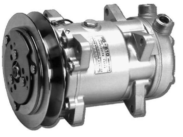
The primary types of compressors used in the mobile HVAC industry are piston (most usable; see Fig. 4), rotary (work like rotary engines), and scroll (work like superchargers).
The compressor is the heart of the AC system. Its primary function is to compress cool, low-pressure vapor and pump out high-pressure hot vapor. The compressor draws low-pressure, low-temperature refrigerant gas from the evaporator. Most mobile AC compressors are engine-driven devices. The higher the engine’s RPM, the greater the compressor output. New electrified mobile HVAC systems equipped with electrical hermetic compressors are described in the entry “Mobile HVAC Systems: Fundamentals, Design and Innovations”, of this topic.
The main cause of compressor failure is lack of lubrication. A normal rule about the required amount of oil in refrigerant is about 200-250 g of oil for every 1 kg of refrigerant in the system. The refrigerant oil level must be maintained for proper lubrication and sealing of the compressor.
Fig. 4 Piston type compressor.
Fig. 5 (A) Tube and fin condenser and (B) parallel flow condenser.
Condenser
The two major types of condensers are tube and fin (Fig. 5A) and parallel flow condensers (Fig. 5B). There are also serpentine-type condensers, which usually are not used as often as the other two types. Primary condenser functions are to release enough heat to the outside air to cool the refrigerant from a hot gas to a less-hot liquid. The condenser must have air blowing across it at all times by means of a fan and fan shroud.
The condenser allows for the removal of heat or energy from the truck cab or the vehicle’s inside compartment to provide a more comfortable less humid environment.
As mentioned above, while flowing through the condenser, refrigerant changes its phase from vapor to liquid via the removal of heat into the cooler outside air. Refrigerant R134a, which is used mostly in automotive applications, changes its vapor phase to liquid phase at 49°C at a constant pressure of 1172 kPa. The condenser actually operates in three modes: desuperheating the inlet refrigerant gas, condensing the saturated vapor, and subcooling the liquid refrigerant. The condensing portion requires the greatest surface area, followed by the other two areas.
Under normal operating conditions, the temperature differential between the refrigerant going into the condenser and coming out of the condenser is about 5°C. The condenser is usually trouble free, but two problems may occur. Cracks and dents, which are nonrepairable, cause leakage and external blockage of the fins via debris that reduces the capability of the fins to cool properly.
Receiver/Dryer
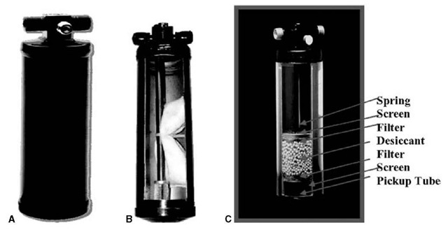
The TXV system (Fig. 2) is equipped with a receiver (filter)/dryer. The primary functions of the receiver (filter)/ dryer (Fig. 6A) are to filter liquid refrigerant, to act as a moisture remover (to absorb moisture), and to serve as a temporary storage unit for liquid refrigerant until it is needed by the system. There are two types of dryers: bag (Fig. 6B) and water (the most common; Fig. 6C). The basic parts of the receiver/dryer are shown in Fig. 6C. The necessity of removing moisture from refrigerant stems from the fact that a chemical reaction between refrigerant and water creates acid—in particular, R134a + water = hydrofluoric acid. Under normal operating conditions, the temperature differential between the refrigerant going into the dryer and coming out of it is about 1 °C-2°C. If frost occurs on the dryer when the system is in operation, it becomes plugged, and it will need to be replaced.
Expansion Valve
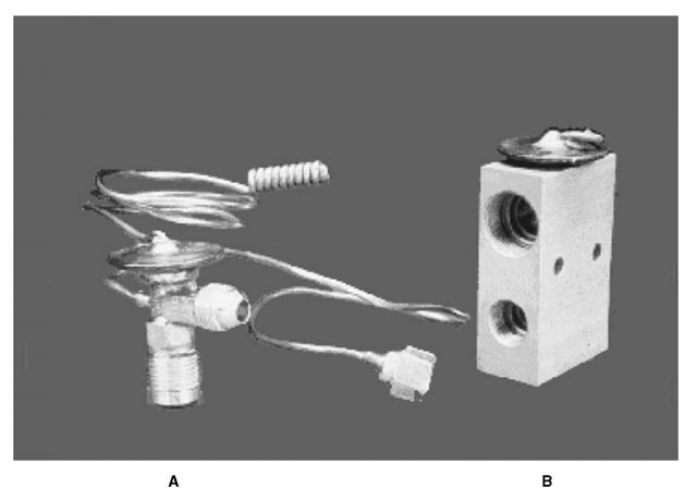
A TXV device meters refrigerant flow to the evaporator and protects the compressor from liquid refrigerant. The schematic of a TXV system is shown in Fig. 2. There are two types of TXV devices: capillary bulb (externally equalized; Fig. 7A) and block (internally equalized; Fig. 7B).
Fig. 6 (A) Receiver/Dryer, (B) bag type receiver/dryer, and (C) water type receiver/dryer.
Fig. 7 (A) Bulb type or externally equalized TXV and (B) block type or internally equalized TXV.
The expansion valve controls the amount of refrigerant sprayed into the evaporator; otherwise, liquid refrigerant would be allowed to enter the compressor, which could cause severe damage. The valve responds to changes in heat load conditions, and actually, TXV operates in response to superheat. Increased heat load causes the valve to open, which allows more refrigerant to flow through. A thermostatic bulb senses the evaporator outlet tube’s temperature (externally equalized) or the evaporator inlet tube’s temperature (internally equalized). The medium in the bulb (usually, refrigerant) exerts pressure on the diaphragm. An increase in temperature (heat load) causes the diaphragm to open, thereby increasing flow. A decrease in temperature causes the diaphragm to close, decreasing refrigerant flow accordingly. Under normal operating conditions, the valve is hot at the inlet and cold at the outlet, and the temperature differential between refrigerant going into the valve and coming out of it is about 4°C-6°C.
A TXV device holds a preset superheat by modulating the refrigerant flow mechanically via a diaphragm, whereas an EXV modulates refrigerant flow electronically, using pulse width modulation or a stepper motor. The superheat can be controlled between 0.5 and 11°C. This device can maximize the AC performance; however, the EXV is significantly more expensive than TXV and less reliable, which can cause an increase in warranty costs.
Orifice Tube
A schematic of an OT system is presented in Fig. 3. The orifice tube (Fig. 8) is nothing more than a piece of copper tubing. This device is a calibrated tube that meters the liquid refrigerant and regulates its flow to satisfy evaporator demand. OTs are color coated to ensure proper replacement. The orifice flow rate is affected by the amount of subcooling out of the condenser. The greater the subcooling, the higher the refrigerant flow rate. Because the OT size is fixed, its size is optimized by maximizing the system performance at high, moderate, and low evaporator load at appropriate compressor speed. Under normal operating conditions, the tube is hot at the inlet and cold at the outlet. There is a large temperature differential between refrigerant going into the OT and coming out of it—about 30°C-80°C. The inlet of the OT is equipped with a screen to protect the evaporator and the compressor from debris and from contaminated refrigerant. Blockage of this screen could cause failure of the whole AC system, because the system will be cycling very rapidly.
A variable orifice tube (VOV) differs from fixed OT in that it is capable of varying the refrigerant flow restriction through the tube in response to the refrigerant temperature exiting the condenser. (During vehicle idling time, the refrigerant temperature is high, and the restriction is greatest; at vehicle highway speed, the refrigerant temperature is low, and the restriction is lowest.) VOV expansion is not used much because its advantages over fixed OT are not significant, and the cost is much higher.
Fig. 8 Orifice tube.
The advantages and disadvantages of an OT system vs a TXV system will be discussed later in this section.
Accumulator
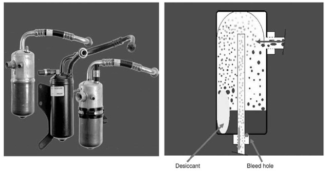
An OT system (Fig. 3) is equipped with an accumulator. Accumulators (Fig. 9) vary in style, but they all do the same job and do it the same way. The accumulator is a liquid vapor separator that stores (accumulates) excess refrigerant that comes out of evaporator so that it does not reach the compressor. Usually, accumulator contains desiccant that dries refrigerant by absorbing moisture from it. The accumulator also filters refrigerant. When the accumulator operates normally, it will be cold.
Evaporator
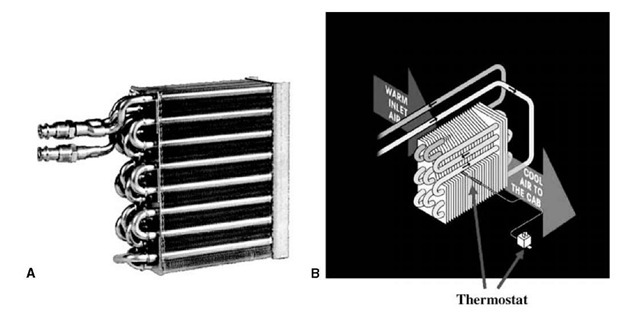
The evaporator is a refrigerant/air heat exchanger in which the liquid refrigerant absorbs the heat that is transferred from the air passing over the evaporator. A blower pulls cab or fresh air through the evaporator (Fig. 10B), where the refrigerant absorbs heat in the air. The cool air is pushed back into the cab and either blows free or distributed through the ductwork. So the evaporator’s duties are to absorb the heat, dehumidify the air, and filter the air. A large number of evaporator types exists in the mobile AC industry. The four basic types of evaporators are: plate fin; tube and fin (Fig. 10A); serpentine; header tube and spacer. There are other types of evaporators as well. In the entry “Mobile HVAC Systems: Fundamentals, Design and Innovations”, of this topic the evaporator capacity calculation and design-optimization approaches will be discussed.
Under normal operating conditions, evaporator in and out lines are cold, and the temperature differential between refrigerant going into the coil and coming out of it is about 3°C-6°C. Basically, the evaporator confirms that the AC system is performing to expected specifications by measuring the air temperature as it leaves the heat exchanger.
Fig. 9 Accumulators.
Fig. 10 (A) Tube and fin evaporator and (B) evaporator performance schematic.
The Supporting Cast
Thermostats
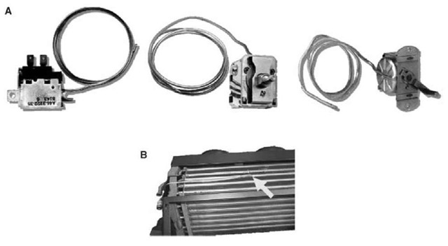
Thermostats (Fig. 11A) sense the evaporator surface and protect coils from freezing (also see Fig. 10A). The three basic types of thermostats are rotary, cable controlled, and fixed setting. Thermostats turn the clutch on and off by sensing evaporator temperature. A probe inserted into the evaporator (Fig. 11B) measures evaporator surface temperature (only the last 0.1 m of the tube is sensed) and turns the clutch on and off (disengaging and engaging the compressor) by sensing this evaporator temperature. The tip must be close to the coldest spot of the evaporator. This spot is usually determined by testing the unit on the test bench (calorimeter). The location of the coldest spot depends on the airflow rate and air profile, HVAC unit configurations, and evaporator design.
Pressure Switches
Most of the AC systems have High and Low pressure switches (Fig. 12) that protect compressor/system against too low or too high pressure by disengages compressor at set low or set high pressure accordingly. Some vehicles have a third high-side pressure switch for cycling condenser fan to cool the condenser.
Electrical System Basics
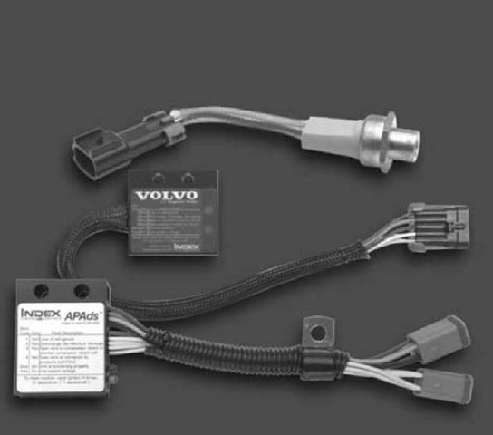
An HVAC system electrical circuit includes On/Off switch, Thermostatic switch, Pressure switches (Low-side low pressure, High-side low pressure, High-side high pressure), Compressor Clutch. Recently a few electronic compressor/system protection devices have been introduced (Fig. 13).
Fig. 11 (A) Rotary, cable controlled, and fixed setting thermostats and (B) evaporator with installed thermostat’s probe.
Fig. 12 Pressure switches.
Fig. 13 Compressor / AC system protection devices.
These devices protect the AC system against low and high pressures, sense low refrigerant in the system, identify low voltage, measure some other refrigerant system parameters, and generate special codes when any of those parameters goes to a dangerous range and shut off system accordingly.
A few other supporting parts are fittings, hoses, and water/heater valves.
TXV System vs OT System
The expansion valve is a much more complex device than the orifice tube, and it offers a wider range of control. However, our experience shows that this advantage of the TXV system is overridden by many problems that arise. These problems are listed below. The expansion valve is the leading source of AC system failure and, thus, the highest warranty item. An OT system allows the use of all evaporator surfaces for heat transfer, whereas a TXV system uses a significant part of the evaporator surface for superheating refrigerant. The expansion valve controls the flow of the liquid refrigerant entering the evaporator relative to the amount of superheat in the refrigerant gas leaving the evaporator. Because the TXV operates in response to superheat, part of the evaporator must be used to superheat the refrigerant gas. The higher the superheat (0.5°C-11°C), the more of the evaporator surface is used for superheating.
Another problem that arises in a TXV system is so-called system hunting. The system goes rapidly on and off, which alternately starves and overfeeds the evaporator. There can be multiple reasons for hunting: A valve is oversize; the factory-set TXV superheat is too low; the suction line is too small; and so on. Our experience and apple-to-apple testing results show that the OT/accumulator-design systems allow up to 2°C-3°C better performance on the air side over TXV design. (The OT system has a temperature differencial between evaporator air in/out that is 2°C-3°C better.) Last but not least, the advantage of the OT system is that it takes more charge because of accumulator use, which allows a longer period between system required to add charge due to permeation through hoses and other small leaks.
