Abstract
This article will focus on considerations—often overlooked—which can have a significant impact on measurements used in energy management. Users will learn how to optimize the accuracy and repeatability of gas and steam flow measurements, minimize flowmeter permanent pressure loss (PPL), and optimize temperature measurement accuracy. Methodologies and/or software tools will be presented that allow the user to quantify the impact of their existing practice and any ROI from adopting the recommended practice.
IMPROVE FLOW MEASUREMENT
Accuracy and Repeatability
Accurate flow measurement is vital to prevent billing disputes in custody transfer applications. Repeatable gas flow rates help optimize combustion[1] and compressor efficiency.[2] Steam and water flow rates are used in the “second and third elements” of feed-water control, and help improve efficient control of heat transfer processes. For all of these fluids, accurate and repeatable internal allocation meters are needed to evaluate the effectiveness of initiatives for controlling energy usage, identify areas for improvement, or detect problems such as leaks. In plants with multiple boilers or compressors, flow measurements are used to determine unit efficiencies, helpful in deciding which units to base load and which to swing.
What should users do to improve the accuracy and repeatability of their flow measurements? Obviously, worn or damaged equipment should be replaced. However, even with new equipment, significant problems are commonly found when the flowmeters are not correctly installed and when gas and steam flows are not density compensated.
FIXING COMMON FLOWMETER INSTALLATION PROBLEMS
Not Enough Straight Pipe
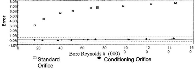
Most flowmeter technologies require straight pipe up- and downstream of the flowmeter to ensure that the flow is well “conditioned” (Table 1). Unfortunately, standards defining these requirements have evolved over time, so many existing installations do not have enough straight pipe. This can cause severe flow errors which are not necessarily consistent (“bias”), as they can vary over the flowrate (Fig. 1). Inserting sufficient straight pipe may not be practical or cost-effective, and flow “conditioners” and “straighteners” increase installation cost and cause high pressure losses.
Newer flow technologies require less straight pipe than “traditional” devices such as orifice meters. For example, Coriolis meters do not require any straight pipe, though the meters themselves can be large and heavy. Magnetic and vortex flowmeters also typically require much less straight pipe than an orifice meter. Vortex meters are often preferred in applications with dirty fluids or wet steam, since they rarely suffer from erosion and newer designs are non-clogging. Unfortunately, many users have avoided vortex technology in the past due to its lack of flexibility when compared with an orifice plate. If the flow range used to size an orifice meter is incorrect, or if it changes over time, the user can usually accommodate the new flow range by re-ranging the pressure drop (DP) transmitter, and possibly replacing the plate. With a vortex meter, the user would not only need to change the entire body—even this is not too expensive, since presumably the old meter can be re-used in another application—but change the piping. The vortex meter requires straight up- and downstream piping, of the same dimension as the meter itself.
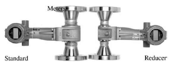
Newer reducer vortex meters avoid this problem (Fig. 2). With these devices, the supplier welds on reducing and expanding flanges, and in a flow lab calibrates out any impact on accuracy. To replace an existing meter with a reducer meter (or vice-versa), the user could simply replace the meter—no changes to piping.
One reason users have traditionally preferred DP-flow-meters to other technologies is that the DP-flowmeter can be easily verified. A user who is not confident that a DP-flowmeter is accurate can simply:
Table 1 Required straight pipe (orifice meter, B = 0.6), per ISO 5167
| Required straight pipe diameters | ||
| Upstream | ||
| disturbance | Upstream | Downstream |
| Single elbow | 18 | 7 |
| Two elbows, | 26 | 7 |
| same plane | ||
| Two elbows, out | 48 | 7 |
| of plane | ||
• Physically inspect the primary element (plate, Annu-bar, venturi, etc.) to ensure no damage.
• Verify the calibration constant for the primary element (beta ratio, etc.).
• Using a pressure source, verify that a simulated zero and full-span DP input into the secondary element (DP transmitter) provides the correct 4-20 mA output.
The same approach is available on newer vortex flowmeters:
• Physically inspect the vortex shedder bar for damage or coating.
• Verify the calibration constant for the shedder bar (^-factor).
• Using a hand-held communicator, verify that a simulated zero and full-span frequency input provides the correct 4-20 mA output.
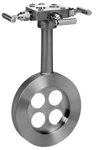
Newest of all is the “conditioning plate,” shown in Fig. 3. This device provides comparable accuracy and pressure loss to an orifice plate, but with only two diameters of straight pipe. Since the conditioning plate directly replaces the existing plate, reusing the same transmitter and taps, this is usually the most cost-effective approach to fixing the accuracy of an existing installation.
In new installations, eliminating the need for straight pipe usually allows the entire flowmeter to be located in an accessible location, minimizing costly and troublesome impulse lines.
Orifice Plate Misalignment
Most users periodically remove and inspect key orifice plates to ensure that they have not eroded. While worthwhile, this introduces the risk that the plate will not be correctly centered in the pipe when it is re-installed. Unless the user is using a mechanism which is inherently self-centering—such as the compact orifice shown in Fig. 3—centering errors of +1/4″ are common. While not significant in large lines, they can cause 3%-4% flow error in a 2″ line.[4]
DENSITY COMPENSATION OF GAS AND STEAM
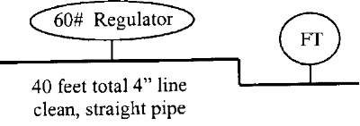
In steam and gas flow applications, the user needs mass flow—evidenced by the use of mass units such as pound per hour or kilogram per second, or “standard” units—standard cubic feet per minute (SCFM), normal cubic meters per hour (NCMH). By assuming that the density is fixed, the user can obtain mass flow by multiplying this density by the volumetric flowrate measured by, for example, the DP, vortex, ultrasonic, or turbine flowmeter. Unfortunately, density is never constant in even the simplest of applications. Fig. 4 shows a schematic of a system in which minimal pressure or temperature variation is expected—steam flow out of a new, pilot-operated regulator, followed by two elbows and a short length of clean, straight pipe.
As calculated1-5-1 by the freeware P&T.xls spreadsheet, pressure variation in this simplest of applications can be up to 2.5 psi, leading to a non-repeatable flow error of 4%. Because the relationship between pressure loss and flowrate is exponential, if flowrate is halved, the DP will quarter; if it doubles, it will quadruple. As a result, the user can receive steam of widely varying density—and hence, mass flowrate—on a minute-by-minute basis.
Fig. 1 Flow error from insufficient straight pipe (orifice meter).
Fig. 2 Vortex meters.
Temperature can also vary, even with saturated steam. As the steam flows, it loses pressure to friction, but— assuming well-insulated pipes—cannot lose enthalpy. This means that it must gain superheat, further reducing density. Temperature variation is even more significant with gases, since they are often sourced from ambient (outside) air, and gas pipes are rarely insulated.
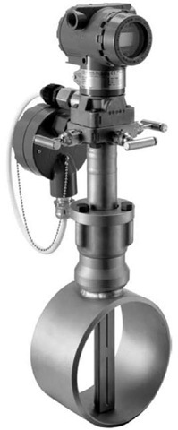
To eliminate the impact of these variations, the “best practice” for any gas or steam flow application is to continuously measure pressure and temperature, and calculate density. Since no real gas is ideal, actual gas compressibility must be calculated using standards, such as AGA-3, ISO 5167, or steam tables. Fig. 5 shows a “multivariable” transmitter that measures differential pressure, line pressure, and temperature, and includes an integrated flow computer that calculates mass flow. The transmitter is shown integrated with an Annubar primary element.
Fig. 3 Conditioning plate—compact orifice paddle-style plate (with integral manifold).
Fig. 4 Pipe schematic.
Minimize Flowmeter Permanent Pressure Loss
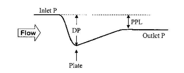
Fig. 6 shows a typical fluid pressure diagram for a differential pressure flowmeter. As the fluid enters the restriction, its pressure falls, creating a differential pressure (DP). This temporary DP (DP = 100in H2O) is measured by the differential pressure transmitter and related to the flowrate via Bernouilli’s Law of conservation of momentum. Once the fluid exits the restriction, some of this pressure is recovered—the unrecovered pressure is the PPL. Permanent pressure loss for common industrial flowmeters can range from zero to greater than 20 psi.
In some applications, flowmeter PPL has no value. Obvious examples include flowmeters that are inline with mostly closed regulators or control valves. In the case of a mostly closed control valve, if the PPL through the flowmeter is reduced, the additional fluid pressure will simply be “scrubbed off” in the valve. In the case of a regulator, if PPL is too high the flowmeter can simply be moved from a location downstream of the regulator, to upstream of the regulator. Applications where PPL has value fall into three general categories:
Fig. 5 Multivariable™ transmitter with integral Annubar
Fig. 6 Pressure loss through flowmeter.
Increase in fluid pressure and/or flowrate = increased production rate.
Flowmeter inline with a variable speed/frequency drive = reduced energy cost.
New projects—smaller pumps and compressors = reduced capital cost.
Once the user identifies applications where reducing flowmeter PPL can provide value, the next step is to quantify the ROI achievable by replacing the existing or proposed technology with low-PPL technology.
Special attention should be paid to gas and steam flows with variable pressure. In most applications, demand for the gas or steam is based on mass flow. In other words, at a given production rate an application will require a certain NCMH of gas, or kilogram per second of steam. If inlet pressure is reduced, to obtain this required mass flow the volumetric flow must increase, increasing velocity and PPL. Consider an example—if inlet pressure is halved, PPL will quadruple through the meter, due to the squared relationship. While this may seem extreme, in many applications header pressure falls because demand—and flow rate—is high. To be safe, users should always calculate worst-case PPL at minimum line pressure as well as maximum mass flowrate.
COMPARING FLOW TECHNOLOGIES
In applications where the economic value of the average PPL is significant, or the worst-case PPL frequently limits production rate, the user should consider replacing a high-PPL technology with a low-PPL technology. The actual PPL of a specific flowmeter in a specific application is normally determined using meter-specific software. For standard devices such as orifice plates, this software is available from suppliers and third parties. As described above, the user must usually add the pressure loss from any required line-size pipe reduction/expansion to the software’s calculated meter PPL.
In water applications where minimizing PPL is important, the recommended flow technology is usually the magnetic flowmeter, since it suffers from zero PPL. In gas and steam flow applications, the averaging pitot tube (“Annubar®”) is usually the best technology. When compared with older round or curved designs, newer “T” designs provide much stronger signals, are easier to install, and much less likely to plug. As an insertion technology, they are also very cost-effective in larger line sizes, and are sometimes used for that reason in large water lines.
Optimize Temperature Measurement
Many industrial applications that consume energy do so to maintain a process at a certain temperature. If that temperature is measured inaccurately, the process can be under-heated (or cooled), possibly impacting quality or safety, or over-heated (or cooled), wasting energy.
IMPROVE ACCURACY OF TEMPERATURE MEASUREMENT
Resistance temperature detectors—RTDs—are usually specified in industrial applications that require high accuracy. Resistance temperature detectors rely on the principle that, for certain metals such as platinum, the resistance of the metal is linearly proportional to its temperature. Most users understand the need to compensate for resistance contributed by the lead wires, hence the widespread adoption of 3-wire, or even better, 4-wire RTDs. Less well understood is the need for “sensor matching.”
When an RTD is connected to a transmitter or distributed control system (DCS) input, the user configures the transmitter to expect a certain sensor “type”—for example, “Platinum 100 ohm RTD.” The transmitter or DCS uses this to convert measured resistance to temperature, using the IEC-751 standard. Unfortunately, no real sensor provides this ideal performance in the real world, and in fact the IEC-751 standard includes a tolerance which can exceed 3°F at higher process temperatures.[7] In applications where ignoring this “sensor interchangeability error” will reduce process safety or efficiency, the user needs to eliminate it by using “sensor matching.” To accomplish this, the supplier of the RTD provides “Calendar van-Dusen” constants that define the “real-world” performance of a given individual sensor. These actual constants are then configured into the transmitter, eliminating the sensor interchangeability error and improving accuracy.
REDUCE COST OF TEMPERATURE MULTIPLEXING
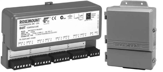
Most energy management projects include a large number of new temperature monitoring points. Direct-wiring these points back to a central DCS or programmable logic controller (PLC), or using a large number of transmitters, can be cost-prohibitive. Instead, many users are using high-density multiplexers. Newer multiplexer solutions (Fig. 7) use industry standards for communication, such as Foundation fieldbus and Modbus, avoiding proprietary devices with their risk of long-term obsolescence.
Fig. 7 High density, standards-based temperature multiplexer.
CONCLUSION
As users look to better manage energy flows, some often-overlooked best practices that should be adopted include:
• Ensure sufficient straight pipe or use conditioning orifice plates or reducer vortex meters.
• Ensure correct orifice plate centering, or use self-centering compact orifice meters.
• Density compensate gas and steam flows, using multivariable transmitters.
• Minimize flowmeter PPL by using averaging pitot tubes (Annubar).
• Optimize temperature accuracy by using Callendar-Van Dusen sensor matching.
• Reduce cost and avoid obsolescence by using standards-based temperature multiplexers.
