Abstract
Many commercial and industrial facilities use boilers to produce steam or hot water for space heating or for process heating. Boilers are typically major users of energy, and any person involved in energy management needs to know how a boiler works and how the performance of a boiler can be maintained or improved. This article outlines the types of boilers used to heat facilities, while providing an overview of basic boiler controls and the parameters that affect energy efficiency.
INTRODUCTION
A boiler is a closed vessel intended to heat water and produce hot water or steam through the combustion of a fuel or through the action of electrodes or electric resistance elements. Many commercial and industrial facilities use boilers to produce steam or hot water for space heating or for process heating. Boilers are typically major users of energy, and any person involved in a facility’s energy management needs to know how a boiler works and how the performance of a boiler can be maintained or improved. In particular, it is important to know what parameters of a boiler system are the most important. For fossil fuel-fired boilers, the combustion efficiency is the major parameter of interest; this is most often controlled by providing the optimum amount of combustion air that is mixed with the fuel. Thus, understanding boiler control systems is extremely important. Steam and hot water boilers are available in standard sizes from very small boilers for apartments and residences to very large boilers for commercial and industrial uses.
BOILER TYPES
Boilers are classified by water temperature or steam pressure. They are further classified by the type of metal used in construction (cast iron, steel, or copper), by the type of fuel or heat element (oil, gas, or electricity), or by the relationship of fire or water to the tubes (i.e., firetube or watertube).
- Low-pressure boilers are those designed to produce steam up to 15 psig or hot water up to 250°F with pressures up to 160 psig.
- Medium- and high-pressure boilers produce steam above 15 psig or hot water above 160 psig or 250°F or both.
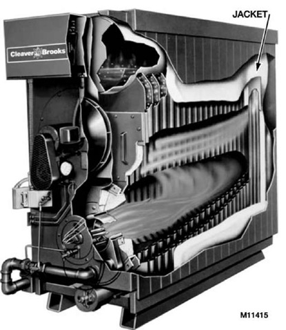
Boilers are typically constructed of cast iron or welded steel. Cast iron boilers (Fig. 1) are made of individually cast sections and are joined together using screws or nuts and tie rods or threaded rivets. The number of sections can be varied to provide a range of capacities.
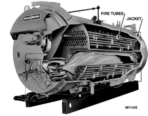
Steel boilers come in a wide variety of configurations. They are factory-assembled and welded and shipped as a unit. Fig. 2 illustrates a firetube boiler. The fire and flue gases are substantially surrounded by water. The products of combustion pass through tubes to the back then to the front and once more to the back before finally exiting at the front. This makes it a four-pass boiler. Firetube boilers are manufactured in many other configurations such as:
- External firebox—The firebox is not surrounded by water.
- Dry back—Firetubes are directly available from clean-out doors at the back of boiler.
- Scotch-Marine—Employs low water volume and has a fast response.
Watertube boilers are steel body boilers used for high capacity requirements of more than 2 million Btu per hour (Btu/h). Watertube boilers use a water-cooled firebox which prolongs the life of furnace walls and refractories.
Fig. 1 Typical cast iron boiler (watertube).
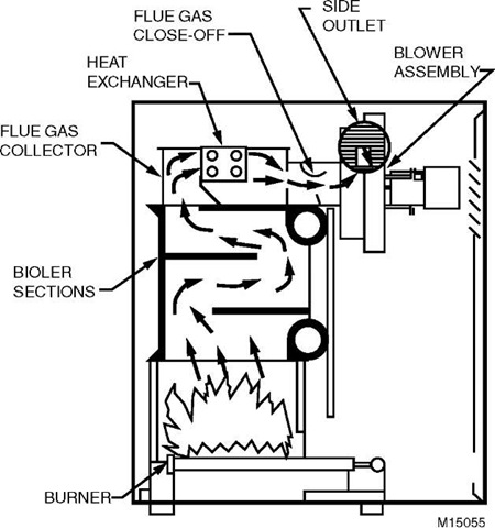
Modular boilers are small, hot water boilers rated from 200,000 to 900,000 Btu/h input. These boilers are available with gross efficiencies of 85% or higher. Fig. 3 shows the features of a typical modular boiler. These boilers are often used in tandem to provide hot water for space heating and/or domestic hot water. For example, if the designed heating load were 2 million Btu/h, four 600,000 Btu/h (input) modular boilers might be used. If the load were 25% or less on a particular day, only one boiler would fire and cycle on and off to supply the load. The other three boilers would remain off with no water flow. This reduces the flue and jacket (covering of the boiler) heat losses.
Some modular boilers have a very small storage capacity and very rapid heat transfer so water flow must be proven before the burner is started.
Electric boilers heat water or produce steam by converting electrical energy to heat using either resistance elements or electrodes. Electric boilers are considered to be 100% efficient since all power that is consumed directly produces hot water or steam. Heat losses through the jacket and insulation are negligible and there is no flue.[1]
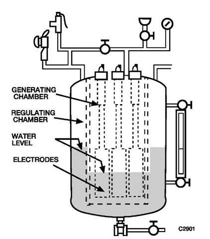
Electrode boilers (as seen in Fig. 4) have electrodes immersed in the water. Electrical current passes through the water between electrodes, and this current and the resistance of the water results in generated heat. Electrode boilers are available in sizes up to 11,000 kW. Resistance boilers have the resistance (heating) elements immersed in, but electrically insulated from, the water and are manufactured in sizes up to 3,000 kW. Electric elements and electrodes are usually grouped to provide four or more stages of heating. A step controller responds to steam pressure or hot water temperature, activating each stage of heating as required to heat the building.
BOILER RATINGS AND EFFICIENCY
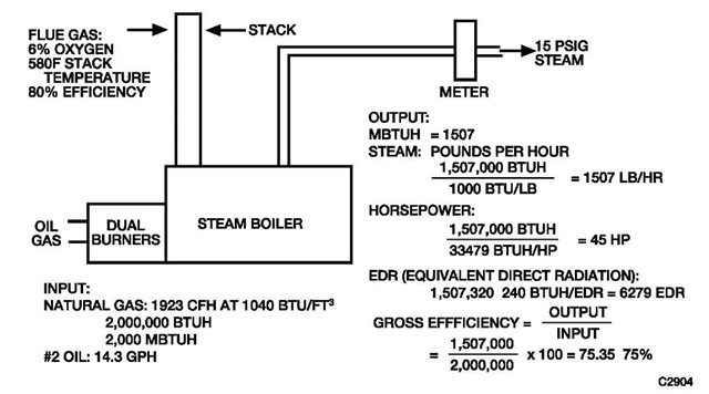
Boilers can be rated in several ways. Fig. 5 shows the commonly used ratings and terms. The terms Btu/h (Btu per hour) and MBtu/h or MB/H (1000 Btu/h) indicate the boiler’s input rate. Input ratings are usually shown on the boiler’s (or burner’s) nameplate. The terms bhp (boiler horse power), EDR (equivalent direct radiation), and pounds per hour (of steam) indicate the boiler’s output rate.
Fig. 2 Typical firetube boiler.
Fig. 3 High efficiency modular boiler.
Gross efficiency of the boiler is the output (steam or water heat content and volume) divided by the fuel input (measured by a fuel meter at steady-state firing conditions). The combustion efficiency, as indicated by flue gas conditions, does not take into account jacket, piping, and other losses, so it is always higher than the gross efficiency.
Fig. 4 Electrode steam boiler.
A testing procedure issued by the U.S. Department of Energy in 1978 measures both on-cycle and off-cycle losses based on a laboratory procedure involving cyclic conditions. The result is called the AFUE (Annual Fuel Utilization Efficiency) rating, or seasonal efficiency, which is lower than gross efficiency.
COMBUSTION IN BOILERS
When gas, oil, or another fuel is burned, several factors must be considered if the burning process is to be safe, efficient, and not impact the environment. The burning process must adhere to the following guidelines:
1. Provide enough air so that combustion is complete, and undesirable amounts of carbon monoxide or other pollutants are not generated.
2. Avoid excess air in the fuel-air mixture which would result in low efficiency.
3. Completely mix the air with fuel before introducing the mixture into the firebox.
4. Provide safety controls so that fuel is not introduced without the presence of an ignition flame or spark and so that flame is not introduced in the presence of unburned fuel.
5. Avoid water temperatures below the dewpoint of the flue gas to prevent condensation on the fireside of the boiler.
Combustion can be monitored by flue gas analysis. For large boilers, over 1,000,000 Btu/h, the analysis is typically continuous. For small boilers, flue gas is analyzed periodically using portable instruments. Flue gas composition analysis routinely measures the percentage of CO2 (carbon dioxide) or 02 (oxygen), but generally not both. Ideal CO2 concentration is in the 10%-12% range. The percentage of oxygen remaining is the most reliable indication of complete combustion. The ideal 02 concentration in the flue gas is in the 3%-5% range. Lower concentrations are impractical and often unsafe. Higher 02 concentrations mean that an excessive quantity of air is being admitted to the combustion chamber and must be heated by the fuel. This excess air passes through the boiler too quickly for the heat to be efficiently transferred to the water or steam, and thereby reduces the combustion efficiency. CO2 measuring instruments are simpler and cost less than 02 measuring instruments.
The CO2 or 02 concentration, plus the stack temperature, provides a burner combustion efficiency in percent— either directly or by means of charting. This combustion efficiency indicates only the amount of heat extracted from the fuel. It does not account for excess heating of combustion air, or losses from leaks or the boiler jacket, among other factors.
For oil-fired boilers, the oil burners are usually of the atomizing variety, that is, they provide a fine spray of oil. Several types of these oil burners exist:
- Gun type burners spray oil into a swirling air supply.
- Horizontal, rotary burners use a spinning cup to whirl oil and air into the furnace.
- Steam- or air-atomizing burners use high pressured air or 25 psig steam to break up the oil into fine droplets.
For modulating or high/low flame control applications, the rotary or steam/air-atomizing burners are most common.
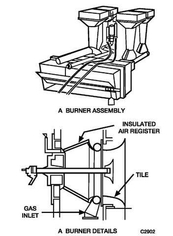
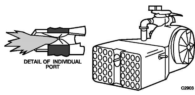
For natural gas-fired boilers, the two typical types of gas burners are the atmospheric injection burner and the power type burner. The atmospheric injection burner uses a jet of gas to aspirate combustion air and is commonly used in home gas furnaces and boilers. The raw-gas ring burner (refer to Fig. 6) is an atmospheric injection burner. Power burners (refer to Fig. 7) use a forced-draft fan to thoroughly mix air and gas as they enter the furnace. Common power burner applications are in the commercial and industrial sectors.
BASIC BOILER CONTROLS
Boilers have to provide steam or hot water whenever heat is needed. A conventional BMCS (boiler management control system) is often set to provide a continuous hot water or steam supply between October and May at anytime the OA (outside air) temperature drops to 60°F for more than 30 min and an AHU (air handling unit) is calling for heat. The BCMS should include a software on/ off/auto function. Unlike chillers, boilers can be left enabled at no-load conditions, during which time the water temperature will be held at the designed temperature. Frequent warm-up and shut-down of boilers causes stress buildup. Boiler manufacturers’ recommendations provide specific guidelines in this area of operation.
Fig. 5 Boiler ratings and efficiency.
Fig. 6 Raw gas ring burner.
Fig. 7 Multiport forced-draft gas burner.
Unless a low-limit for water temperature is used, hot water boiler burners are not controlled to provide water temperatures based on outdoor temperatures, because the reset schedules require water temperatures to be supplied below the dewpoint temperature of the flue gas. Some boilers require incoming water temperatures to be above 140°F before going to high-fire. In this case, if a building is using a hot water system and the boiler is locked into low-fire because the incoming water is too cold, the system may never recover.
The following are three ways to control the output of a commercial boiler:
1. On/off (cycling) control
2. High-fire/low-fire control
3. Modulating control
On/off (cycling) control is most common for small boilers up to 1,000,000 Btu/h capacity. The oil or gas burner cycles on and off to maintain steam pressure or water temperature. Cycling control causes losses in efficiency because of the cooling (which is necessary for safety) of the fireside surfaces by the natural draft from the stack during the off, pre-purge and post-purge cycles.
High-fire/low-fire burners provide fewer off-cycle losses since the burner shuts off only when loads are below the low-fire rate of fuel input.
Modulating control is used on most large boilers because it adjusts the output to match the load whenever the load is greater than the low-fire limit, which is usually not less than 15% of the full load capacity. Steam pressure or hot water temperature is measured to determine the volume of gas or oil admitted to the burner.
Boiler firing and safety controls are boiler-manufacturer furnished and code approved. A BMCS usually enables a boiler to fire, provides a setpoint, controls pumps and blending valves, and monitors operation and alarms.
Combustion control regulates the air supplied to a burner to maintain a high gross efficiency in the combustion process. More sophisticated systems use an oxygen sensor in the stack to control the amount of combustion air supplied. Smoke density detection devices can be used in the stack to limit the reduction of air so stack gases stay within smoke density limits. A continuous reading and/or recording of flue gas conditions—O2 concentration percentage, stack temperature—is usually included in the control package of large boilers.
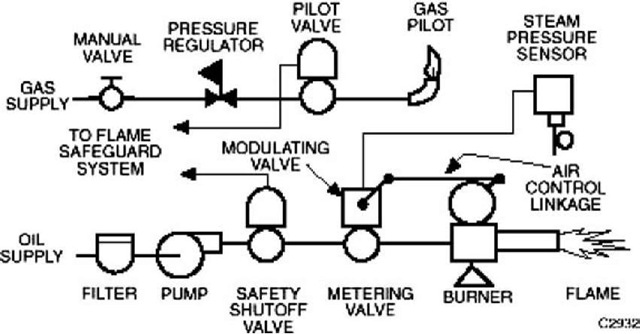
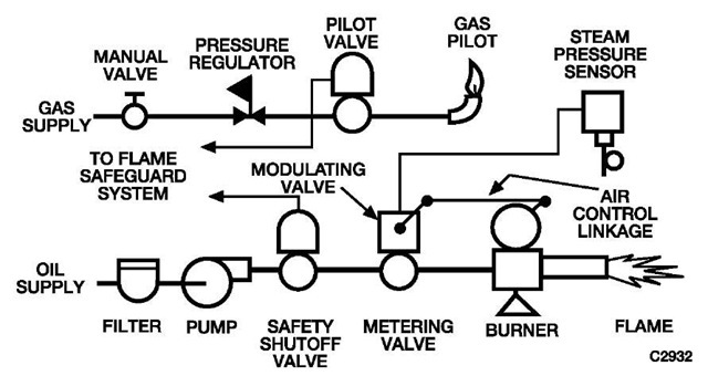
A simple combustion control system contains a linkage that readjusts the air supply from the same modulating motor that adjusts the fuel supply (refer to Fig. 8). There may be a provision to stop the flow of air through the fluebox during the off-cycles.
Flame Safeguard Control
Flame safeguard controls are required on all burners. Flame controls for large burners can be very complicated while controls for small burners such as a residential furnace are relatively simple. The controls must provide foolproof operation—i.e., they must make it difficult or impossible to override any of the safety features of the system. The controls also should be continuously self checked. For commercial and industrial burners, the flame safeguard control generally goes through a series of operations similar to the following.
- Purge the firebox of unburned fuel vapor (prepurge).
- Light the pilot.
- Verify that the pilot is lit.
- Open the main fuel valve.
- Verify that the flame is present as soon as fuel is introduced.
- Cut off the fuel supply promptly if the flame fails.
- Purge the firebox of any unburned fuel after each on-cycle (post-purge).
Fig. 8 Combustion control for rotary oil burner.
Fig. 9 Simple flame safeguard for a gas furnace.
The key to any flame safeguard system is a reliable and fast means of detecting the presence or absence of a flame. Methods of detection include:
- Response of a bimetal sensor to heat (slow response).
- Response of a thermocouple to heat (slow response).
- Flame conductivity (fast, but not reliable response)
- Flame rectification (fast, reliable response).
- Ultraviolet flame detection (fast, reliable response).
- Lead sulfide (photo) cells (fast, reliable response if a flame frequency check is included).
Some sensors can potentially malfunction because of short circuits, hot refractories, or external light sources. Other sensors, like flame rectification and ultraviolet detection, respond to flame only. Flame safeguard systems must be approved by Underwriter’s Laboratory (UL) or Factory Mutual for specific applications. Fig. 9 shows a flame safeguard system commonly applied to small gas boilers or furnaces. The flame of the gas pilot impinges on a thermocouple which supplies an electric current to keep the pilotstat gas valve open. If the pilot goes out or the thermocouple fails, the pilotstat valve closes or remains closed preventing gas flow to the main burner and pilot. The pilotstat must be manually reset.
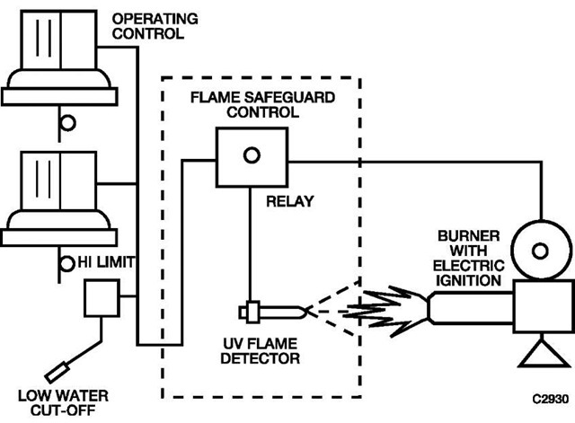
Fig. 10 shows how flame safeguard controls are integrated with combustion controls on a small, oil-fired steam boiler. The ultraviolet (UV) flame detector is located where it can see the flame and will shutdown the burner when no flame is present.
In addition to the combustion, safety, and flame safeguard controls shown in Fig. 10, larger burners often provide additional measuring instrumentation such as:
- Percentage of O2 or CO2 in flue gas (to monitor combustion efficiency)
- Flue gas temperature
- Furnace draft (in inches of water) column
- Steam flow with totalizer or hot water Btu with totalizer
- Oil and/or gas flow with totalizer
- Stack smoke density
CONTROL OF MULTIPLE BOILER SYSTEMS
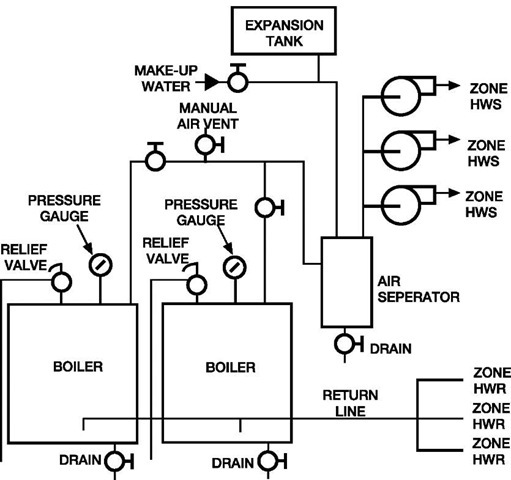
Basic boiler connections for a three-zone hot water system are shown in Fig. 11. In this system, two boilers are connected in parallel. Hot water from the top of the boilers moves to the air separator which removes any entrapped air from the water. The expansion tank connected to the separator maintains the pressure in the system. The tank is about half full of water under normal operating conditions. Air pressure in the tank keeps the system pressurized and allows the water to expand and contract as the system water temperature varies. Water from the boiler moves through the separator to the three zone pumps, each of which is controlled by its own thermostat. In some systems, each zone may have a central pump and a valve. Return water from each zone goes back to the boiler in the return line. Several variations are possible within this type system, but the process is the same. There is no minimum boiler water flow limit in this example.
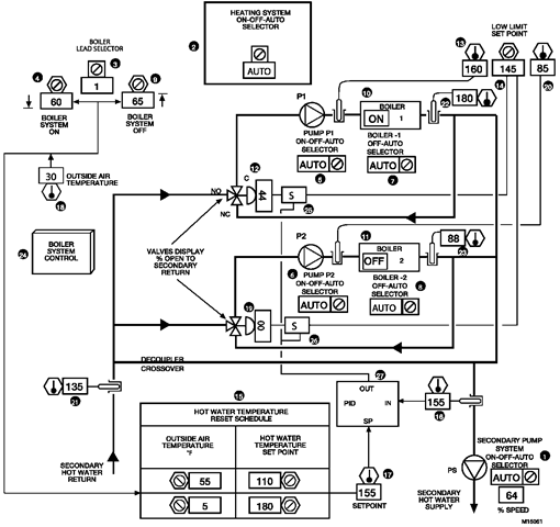
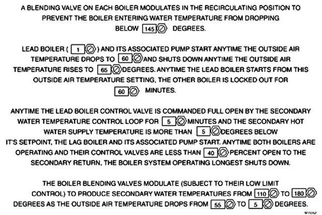
The Dual Boiler Plant Control example in Fig. 12 is a dual boiler plant with high-fire/low-fire controlled boilers. A minimum incoming water temperature of 145°F is required prior to high-fire, water flow must be maintained when the boiler is enabled, and a secondary hot water reset schedule of 110°F water at 55°F OA temperature and 180°F water at 5°F OA temperature. These concepts adapt well for single- or multiple-boiler systems.
Fig. 10 Combustion controls with flame safeguard circuit.
Note: The primary/secondary decoupler is sized for the full secondary flow, and like the chiller plant decoupler, should be a minimum of 6 pipe diameters in length. Unlike the chiller decoupler, normal flow may occur in either direction.
Fig. 11 Typical piping for multiple-zone heating system.
Fig. 12 Dual boiler plant control graphic.
Functional Description
| Item no. | Function |
| 15-18 | Secondary water setpoint reset from OA |
| 19, 20 | Valve modulates to prevent incoming water from dropping below the low-limit setpoint (145° F) |
| 21-23 | Operator information |
| 24 | Icon, selects the Boiler System |
| Control dynamic display (as seen in Fig. 13) | |
| 25, 26 | Software signal selection functions, allows valve to control secondary HW temperature, subject to boiler low-limits |
| 27 | OA reset valve control PID |
Features
1. Full flow through operating boilers
2. Minimum temperature limit on the boiler’s incoming water
3. Variable-flow secondary system with full boiler flow
4. Automatic boiler staging
5. User-friendly monitoring and adjustment
Conditions for Successful Operation
1. Control network, software, and programming to advise the heating plant controller of secondary fan and water flow demands.
2. Interlock and control wiring coordinated with the boiler manufacturer.
3. Control in accord with boiler manufacturer’s recommendations.
4. Proper setpoint and parameter-project-specific settings.
Specification
The heating plant shall operate under automatic control anytime the secondary pump’s on/off/auto function is not “OFF,” subject to a heating system’s on/off/auto software function. The lead boiler, as determined by a software-driven lead-boiler-selection function, shall be enabled anytime the date is between October 1 and May 1, the OA temperature drops below 60°F for greater than 30 min, and an AHU is calling for heat. Each boiler’s primary pump shall have a software on/off/auto function, and each boiler shall have a software auto/off function. The heating plant shall be disabled anytime the OA temperature rises to 65°F for greater than 1 min and after May 1.
BOILER SYSTEM CONTROL
Fig. 13 Boiler system control dynamic display.
Fig. 14 Typical primary-secondary piping for modular boilers.
Anytime the boiler plant is enabled, the lead boiler’s primary pump shall start and, as flow is proven, the boiler shall fire under its factory controls to maintain 180°F. If the lead boiler’s status does not change to “on,” or if flow is not proven within 5 min, the lag boiler shall be enabled.
During boiler operation, a three-way blending valve shall position to place the boiler flow in a recirculating mode until the water entering the boiler exceeds a low-limit value of 145°F, at which time the blending valve shall modulate to maintain the secondary water temperature between 110 and 180°F as the OA temperature varies from 55 to 5°F.
The lag boiler shall be locked out from operation for 60 min after the lead boiler starts. Thereafter, anytime one boiler control valve is commanded full open by the secondary temperature control loop for greater than 5 min and the secondary water temperature is a temperature less than 5°F below the secondary water temperature setpoint, the “off’ (lag) boiler pump shall start. And, upon proving flow, the “off’ boiler shall be enabled to fire under its factory controls to maintain 180°F. The just-started boiler’s blending valve shall be controlled by an incoming 145°F water temperature low-limit sensor and setpoint similar to the lead boiler’s, and subsequently, in unison with the other boiler’s blending valve to maintain the reset, secondary hot-water temperature.
Anytime both boilers are operating and their control valves are less than 40% open to the secondary return line, the boiler and pump that has run longest shall shut down.
Modular Boilers
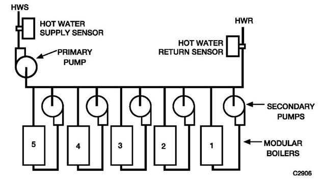
Modular boilers provide heat over a large range of loads and avoid standby and other losses associated with operating large boilers at small loads. Fig. 14 shows a primary-secondary piping arrangement where each modular boiler has its own pump. The boiler pump is on when the boiler is on.
Boilers that are off have no flow and are allowed to cool. Each boiler that is on operates at or near full capacity. Avoiding intermittent operation prevents losses up the stack or to the surrounding area when the boiler is off.
Normal control of modular boilers cycles one of the on-line boilers to maintain water temperature in the supply main to meet load requirements. The supply main’s control sensor cycles the boilers in sequence. If the load increases beyond the capacity of the boilers that are on-line, an additional boiler is started. The lead (cycling) boiler can be rotated on a daily or weekly basis to equalize wear among all boilers or when using digital controls, the program can start the boiler that has been off the longest.
CONCLUSION
In many facilities, boilers represent the most significant pieces of energy consuming equipment. Understanding how a boiler functions, and how it can best be controlled may lead to large energy savings for residential, commercial, and industrial complexes.
