4.2
The line current drawn by induction motors, transformers, and other inductive devices consists of two components: the magnetizing current and the power-producing current.
The magnetizing current is that current required to produce the magnetic flux in the machine. This component of current creates a reactive power requirement that is measured in kilovolt-amperes reactive (kilovars, kvar). The power-producing current is the current that reacts with the magnetic flux to produce the output torque of the machine and to satisfy the equation
T = K<PI
where
T = output torque
0 = net flux in the air gap as a result of the magnetizing
current
1 = power-producing current
K = output coefficient for a particular machine
The power-producing current creates the load power requirement measured in kilowatts (kW). The magnetizing current and magnetic flux are relatively constant at constant voltage. However, the power-producing current is proportional to the load torque required.
The total line current drawn by an induction motor is the vector sum of the magnetizing current and the power-producing current. For three-phase motors, the apparent power, or kilovolt-ampere (kVA) input to the motor, is
![tmpFE-1_thumb[1] tmpFE-1_thumb[1]](http://lh3.ggpht.com/_X6JnoL0U4BY/S1f0-OZf7eI/AAAAAAAAHVA/W-yFmcZDvcQ/tmpFE1_thumb1_thumb.jpg?imgmax=800)
where
IL = total line current VL = line-to-line voltage
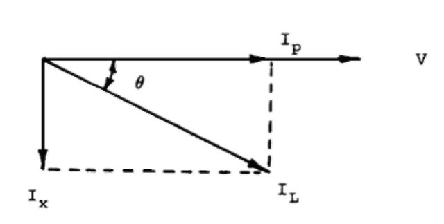
The vector relationship between the line current IL and the reactive component Ix and load component Ip currents can be expressed by a vector diagram, as shown in Fig. 4.1, where the line current IL is the vector sum of two components. The power factor is then the cosine of the electrical angle 6 between the line current and phase voltage.
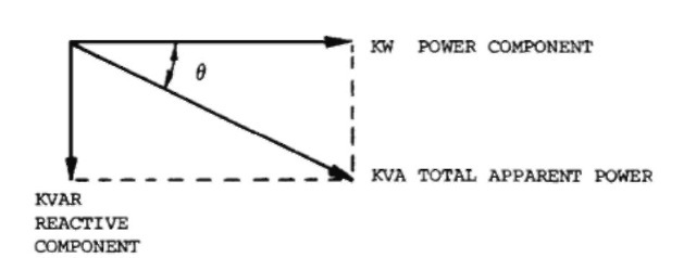
This vector relationship can also be expressed in terms of the components of the total kilovolt-ampere input, as shown in Fig. 4.2. Again, the power factor is the cosine of the angle 6 between the total kilovolt-ampere and kilowatt inputs to the motor. The kilovolt-ampere input to the motor consists of two components: load power, i.e., kilowatts, and reactive power, i.e., kilovars.
The system power factor can be determined by a power factor meter reading or by the input power (kW), line voltage, and line current readings. Thus,
![tmpFE-2_thumb[2] tmpFE-2_thumb[2]](http://lh5.ggpht.com/_X6JnoL0U4BY/S1f0_hJPsBI/AAAAAAAAHVI/dKDR-eQfu9Q/tmpFE2_thumb2_thumb.jpg?imgmax=800)

FIGURE 4.1 Vector diagram of load current for one phase of the motor.

FIGURE 4.2 Vector diagram of power input without a power factor correction.
![tmpFE-5_thumb[1] tmpFE-5_thumb[1]](http://lh4.ggpht.com/_X6JnoL0U4BY/S1f1EesjKXI/AAAAAAAAHVg/tbt41m4X8Dc/tmpFE5_thumb1_thumb.jpg?imgmax=800)
An inspection of the kilovolt-ampere input diagram shows that the larger the reactive kilovar, the lower the power factor and the larger the kilovolt-ampere for a given kilowatt input.
THE POWER FACTOR IN SINUSOIDAL SYSTEMS (Electric Motor)
Next post: WHY RAISE THE POWER FACTOR? (Electric Motor)
Previous post: The Power Factor (Electric Motor)
