8.2
A BLDC machine model is shown in Fig. 8.9. As shown in this figure, R is the phase resistance; L is the phase inductance; and EA, EB, and EC are phase back EMF voltages. The waveforms are shown in Fig. 8.10.
Motor terminal voltage for a three-phase full bridge inverter with six switches and Y-connected motor can be expressed as follows:
![]()
Assuming switches are ideal and the EMF between conducting phases is constant (trapezoidal EMF), the instantaneous armature current can be written as follows:
![]()
We can express the EMF simply as a function of rotor speed:
![tmp3F-11_thumb[1] tmp3F-11_thumb[1]](http://lh3.ggpht.com/_X6JnoL0U4BY/S1ghSNOSnfI/AAAAAAAAHpI/MvMVsjytyWs/tmp3F11_thumb1_thumb.jpg?imgmax=800)
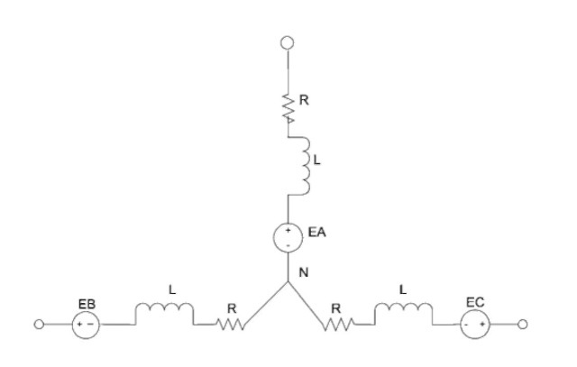
FIGURE 8.9 Equivalent circuit of a BLDC machine.
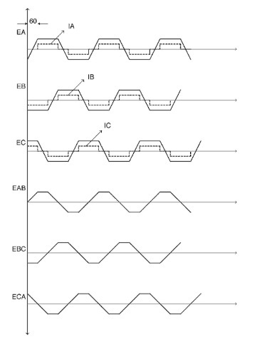
FIGURE 8.10 Voltage and current waveforms as a function of rotor position.
Torque equation is similar to a conventional DC commutator motor and can be written as follows:
![tmp3F-14_thumb[2] tmp3F-14_thumb[2]](http://lh4.ggpht.com/_X6JnoL0U4BY/S1ghWjoZAnI/AAAAAAAAHpg/ufpbEvjFuK0/tmp3F14_thumb2_thumb.jpg?imgmax=800)
The average developed torque can be maximized and torque ripple can be minimized if the EMF voltage waveform has a trapezoidal shape. Trapezoidal waveform can be achieved by switching the MOSFETs or IGBTs in such a way that two-phase windings are always connected in series during the whole conduction period of 60 degrees. In addition, proper shaping and magnetizing of the permanent magnets and stator windings are important factors to obtain the trapezoidal waveform. Owing to manufacturing tolerances, armature reactions, and other parasitic effects, the EMF waveform is never ideally flat. However, a torque ripple below 5% can be achieved.
Power density and torque density are the measures to judge how the active materials of a BLDC motor are best utilized. NdFeB
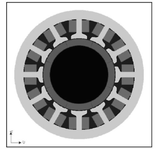
FIGURE 8.11 Geometry of a three-phase, 1-hp BLDC motor.
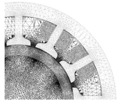
FIGURE 8.12 Enlarged view of the electromagnetic mesh of the three-phase, 1-hp BLDC motor.
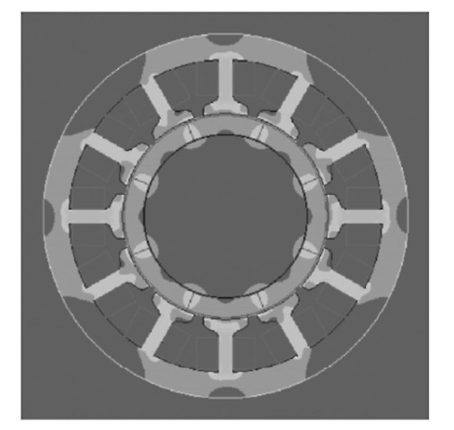
FIGURE 8.13 Magnetic flux density of the three-phase, 1-hp BLDC motor.
magnets offer the highest energy density at reasonable costs. Their major drawback, compared to SmCo, is temperature sensitivity. When using NdFeB magnets, the motor’s temperature must be kept below 170-250°. Since the rotor losses are small, passive cooling is employed for the rotor. The main dimensions (inner stator diameter and effective length of core) for the BLDC are determined by rated power output, air gap magnetic flux density, and armature line current. Geometry of a three-phase, 1-hp BLDC motor is shown in
Fig. 8.11.
Using a finite element (FE) software package such as Maxwell 2D (Ansoft Corp.) a BLDC machine can be analyzed and various solutions presented. The software generates an initial mesh and then refines the solution to achieve the required precision. An enlarged view of the final mesh is shown in Fig. 8.12. Magnetic flux density is shown in Fig. 8.13.
MODELING (Electric Motor)
Next post: BLDC POWER ELECTRONIC DRRIVES (Electric Motor)
Previous post: BLDC MACHINE CONFIGURATIONS (Electric Motor)
