9.2
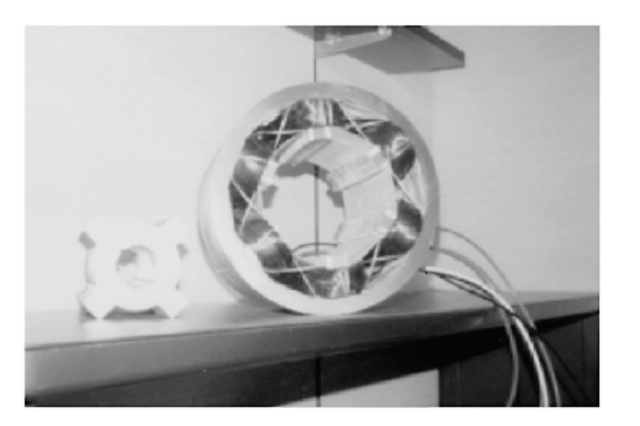
Switched reluctance machines are similar to synchronous machines but with significant distinctive features. They are referred to as doubly salient pole machines as their stator and rotor both have salient poles. This configuration proves to be more effective as far as electromagnetic energy conversion is concerned. Another prominent feature is that there is no coil or permanent magnet (PM) on the rotor. Figure 9.3 shows the rotor and stator of a 10-hp 6/4 SRM with six stator and four rotor poles.
The absence of permanent magnets or coils on the rotor means that torque is produced purely by the saliency of the rotor laminations. The torque is produced with respect to the direction of the flux through the rotor, and hence the direction of the flow of the current in the stator phase windings is not important. The need for unipolar phase current in the reluctance motor results in simpler and more reliable power converter circuits.
9.2.1
Torque Equation
Despite the simple operation of SRMs, an accurate analysis of the motor’s behavior requires a relatively complex mathematical approach. The instantaneous voltage across the terminals of a single

FIGURE 9.3 Rotor and stator of a 10-hp SRM with six stator and four rotor poles.
phase of the motor winding is related to the flux linked in the winding by Faraday’s law,
![tmp51-4_thumb[1] tmp51-4_thumb[1]](http://lh5.ggpht.com/_X6JnoL0U4BY/S1gjoUYnmLI/AAAAAAAAHrI/rWD0CUQH3ms/tmp514_thumb1_thumb.jpg?imgmax=800)
where v is the terminal voltage, i is the phase current, R is the motor resistance, and dip/dt is the flux linked by the winding. We can rewrite this equation as follows:
![tmp51-5_thumb[1] tmp51-5_thumb[1]](http://lh4.ggpht.com/_X6JnoL0U4BY/S1gjp2zUU0I/AAAAAAAAHrQ/Sh8pWTtKi_0/tmp515_thumb1_thumb.jpg?imgmax=800)
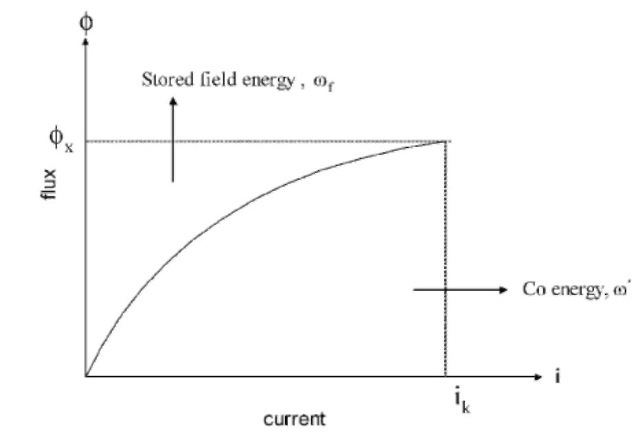
where d<pjdi is defined as the instantaneous inductance L(6,i) and d(f>/di is defined as the instantaneous back EMF Kh(6,i). Figure 9.4 depicts the flux-current characteristic of the machine. The above equation defines the transfer of electrical energy to the magnetic field of the machine. The following equations describe the conversion of the field’s energy into mechanical energy. Multiplying each side of Faraday’s equation by the electrical current gives an expression for the instantaneous power:
vi = Ri2 +
dt

FIGURE 9.4 Flux-current characteristic of an SRM.
The left side of this equation represents the instantaneous electrical-power delivered to the SRM. The first term on the right side represents the resistive losses in the SRM stator winding. If power is to be conserved, then the second term on the right side must represent the sum of the mechanical power output of the machine and any power stored in the magnetic field.
![tmp51-7_thumb[1] tmp51-7_thumb[1]](http://lh3.ggpht.com/_X6JnoL0U4BY/S1gjsZQZtoI/AAAAAAAAHrg/yCM3mrEWOTA/tmp517_thumb1_thumb.jpg?imgmax=800)
Substituting the above torque term, we obtain
![tmp51-8_thumb[1] tmp51-8_thumb[1]](http://lh5.ggpht.com/_X6JnoL0U4BY/S1gjtmG-WWI/AAAAAAAAHro/dkf1mZQIRhg/tmp518_thumb1_thumb.jpg?imgmax=800)
By solving the equations, we get
![]()
We can simplify to
![tmp51-10_thumb[1] tmp51-10_thumb[1]](http://lh3.ggpht.com/_X6JnoL0U4BY/S1gjwFbe3fI/AAAAAAAAHr4/G5K5FJZBypU/tmp5110_thumb1_thumb.jpg?imgmax=800)
It is better to express torque in terms of the current rather then flux; therefore, torque is expressed in terms of coenergy instead of energy:
![tmp51-11_thumb[1] tmp51-11_thumb[1]](http://lh4.ggpht.com/_X6JnoL0U4BY/S1gjxWwupVI/AAAAAAAAHsA/l-vm9evPwic/tmp5111_thumb1_thumb.jpg?imgmax=800)
Wc is defined as the magnetic field coenergy.
![tmp51-12_thumb[1] tmp51-12_thumb[1]](http://lh6.ggpht.com/_X6JnoL0U4BY/S1gjygLnoCI/AAAAAAAAHsI/RNhuc1A15ZE/tmp5112_thumb1_thumb.jpg?imgmax=800)
Differentiation and substituting in the main torque equation,
![]()
![]()
For simplicity, coenergy can be written as
![tmp51-15_thumb[1] tmp51-15_thumb[1]](http://lh3.ggpht.com/_X6JnoL0U4BY/S1gj3NGOZLI/AAAAAAAAHsg/sGfgasbKK0A/tmp5115_thumb1_thumb.jpg?imgmax=800)
After neglecting the saturation, we can write flux and current as
![tmp51-16_thumb[1] tmp51-16_thumb[1]](http://lh5.ggpht.com/_X6JnoL0U4BY/S1gj4VI_WdI/AAAAAAAAHso/FlFF5xrENt4/tmp5116_thumb1_thumb.jpg?imgmax=800)
Substituting in the coenergy equation,
![tmp51-17_thumb[1] tmp51-17_thumb[1]](http://lh6.ggpht.com/_X6JnoL0U4BY/S1gj5_imtPI/AAAAAAAAHsw/MUpmj-tNy5o/tmp5117_thumb1_thumb.jpg?imgmax=800)
The simplified torque equation is obtained as follows:
![tmp51-18_thumb[1] tmp51-18_thumb[1]](http://lh4.ggpht.com/_X6JnoL0U4BY/S1gj6_j4i5I/AAAAAAAAHs4/FuXBrqaDcLI/tmp5118_thumb1_thumb.jpg?imgmax=800)
9.2.2
Characteristics of SRMs
The torque-speed characteristic of an SRM depends on the control used in the machine. It is also easily programmable, which makes the SRM attractive. However, there are some limitations due to the physical constraints such as the supply voltage and allowable temperature rise of the motor under increasing load.
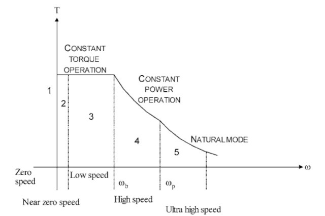
As in other motors, torque is limited by the maximum allowed current and speed by the bus voltage. With increasing shaft speed, a current limit region persists until the rotor reaches a speed where the back EMF of the motor is such that, given the DC bus voltage limitation, we can get no more current in the winding, thus no more torque from the motor. At this point, which is called the base speed, we can obtain constant torque operation in which the shaft output power remains constant at its maximum. At still higher speeds, the back EMF increases and the shaft output power begins to drop. The product of the torque and the square of the speed remains constant in this region. The SRM holds an outstanding benefit over other
machines as the ratio between the maximum speed and base speed in this machine is up to 10, which specifies that the SRM has extended speed constant power operation. The torque-speed characteristic is shown in Figure 9.5.
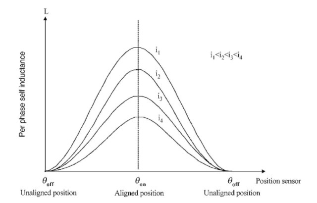
In SRM drives, the phase flux is the sum of the self-flux and the mutual flux. The self-flux is dominated as it goes through mostly iron and two air gaps across the phase poles, while the mutual flux goes to the air gap between the stator poles and interpolar part of the rotor poles. Due to the more effective air gap, there is high reluctance and lower contribution to the phase flux. Hence, the rotor position and related phase currents determine the self-inductance of the phase. Variations in the mutual inductance due to the phase current are practically negligible. There is no variation in self-inductance when the rotor is unaligned, but it decreases when the rotor is near the aligned position. The variation in the mutual inductance is not significant compared to the variations in self-inductance. The inductance characteristic with respect to different rotor positions and different phase current levels is shown in Figure 9.6. Figure 9.7 depicts the flux-current characteristic of

FIGURE 9.5 Torque-speed characteristic of an SRM.

FIGURE 9.6 Self-inductance-rotor position characteristic of an SRM.
an SRM as a function of rotor position. Figures 9.8-9.10 show a flux density map, flux lines, and the wire mesh of a typical 6/4 SRM, respectively.
