ABSTRACT
The loading rate effect on the tensile failure strength of concrete and its constituent materials has been investigated. Concrete is inherently weaker in tension than compression so tensile failure represents the dominant failure mode. Understanding the failure characteristics of concrete, particularly at high loading rate, is important for developing modeling capabilities, in particular for predicting spallation damage and fragmentation. Several concretes, and their constituents, have been investigated at different loading rates to understand the tensile failure behavior as a function of loading rate. In this paper, experimental procedures that were used are discussed, and results from two different tensile testing methods, direct tension and diametric compression (Brazilian/split-tension), are presented for several of these materials.
INTRODUCTION
Tensile failure is a vulnerable failure mode for concrete as it is much weaker in tension compared with other modes of failure such as compression. Typically the tensile strength is an order of magnitude less than the compressive strength. High strain rate tensile testing of concrete is important for weapons effects problems, such as penetration and explosive loading, where the loading rates are very high and tensile failure can occur as spallation damage in a target. Materials can behave differently at high strain rates, so material characterization in this regime is important for developing accurate material models for simulations.
Direct tension experiments produce a nominally uniaxial tensile stress state, however, it can be difficult to implement because of issues associated with gripping the sample. This is particularly the case for brittle materials, such as concrete, where it is not possible to use conventional grips or threaded joints. High strength adhesives can be used to grip normal concrete; however they are not strong enough for testing the new generation of high strength concretes. Notched specimens can be used to reduce the cross-sectional area [1], however, this creates a stress concentration which leads to an under prediction of the tensile strength. Dog-bone specimen geometries are also possible, however these are difficult implement in brittle materials. The diametric compression test, also known as the Brazilian or Split-tension test, offers an alternate test method to indirectly obtain the material tensile response. This test induces tensile stresses within the specimen by point diametric compression of a disc shaped sample. This permits the use of simpler compression testing apparatus to obtain tensile material response data. Other tensile test techniques also include three or four point bend tests and high rate specific spallation experiments [2].
This report presents the tensile strength for various concretes and their constituent materials (mortar and aggregate) using the diametric compression technique. Tests are conducted at high loading rate using a Split Hopkinson Pressure Bar (SHPB) apparatus and intermediate and low loading rates using an Instron hydraulic test machine for comparison. This allows an investigation of the loading rate effects for each of these materials. Direct tension tests at high loading rate have also been conducted for several of the concrete materials to allow a comparison of tensile strengths from the direct tension and diametric compression test methodologies.
MATERIALS
The tensile strengths of five different materials were investigated in this study:
1. SAM35 concrete: a 3500psi (~24MPa) minimum quasi-static unconfined compressive strength concrete produced by the US Engineering and Research Development Center (ERDC) [3]. It contains small limestone aggregate components up to approximately 8mm in size.
2. Mortar: prepared from a commercially available mix – Drypack basic mortar sand and cement, Adelaide Brighton Cement Limited, Australia.
3. Granite: charcoal black granite, Starrett, True Stone Tech Division, MN, US.
4. Ultra High Performance Concrete (UHPC): a reactive powder concrete reinforced with steel fibers of length 12.7mm and diameter 0.2mm, randomly distributed through the concrete at 6.2% by weight [4], samples obtained from Australia.
5. Alcatraz concrete: obtained from a tourist commercial vendor at the Alcatraz prison in San Francisco, California.
The SAM-35 represents a common concrete mix and the mortar and granite are representative of typical concrete constituents (however, the SAM-35 contains limestone aggregate not granite). The UHPC is a new generation high strength concrete which was tested to evaluate its enhanced characteristics.
The diametric compression tests used disc shaped specimens with a nominal thickness of %" (6.35mm). The mortar, UHPC and Alcatraz concrete specimens had a nominal diameter of 20mm, whereas the SAM-35 and granite specimens had a nominal diameter of 1" (25.4mm). Direct tension tests at high loading rate were also performed on the mortar and SAM35 concrete using cylindrical samples with %" diameter and %" length.
The size of the specimen geometry was dictated by the available experimental equipment and was fairly small relative to the size of the aggregrate components in the concrete and the steel fiber distribution for the UHPC. In addition, the material heterogeneity is further amplified in the diametric compression test where only a portion of the sample is in tension. Consequently it is expected that there will be considerable scatter in the results and so a minimum of five tests were conducted for each material at each loading rate.
EXPERIMENTAL METHODOLOGY
Diametric compression test technique
The diametric compression (Brazilian/split tension) test uses a circular disc sample, which is point loaded at diametrically opposite points in compression. This test methodology produces a biaxial stress state where a tensile stress is induced perpendicular to the compressive stress along the loading axis and the material fails in tension. The stress state produced with this loading condition is discussed in detail in [5]. The diametric compression test methodology gives the tensile failure strength of the material, however, no pre or post-peak stress-strain response can be obtained.
A problem with the point loading used in this test methodology, particularly for brittle materials, is that the sample is subject to high stress concentrations at the external load contact points. Thus failure may initiate at these contact points rather than in the induced tensile region in the bulk of the specimen, which invalidates the test. To reduce the stress concentrations at the contact points, wooden bearing strips are recommended for distributing the load in quasi-static diametric compression tests [6,7], however, these are not suitable for high rate tests because of the reflections of stress waves and material impedance effects. For high rate diametric compression tests, other researchers have suggested several techniques to overcome this problem, both with the objective of spreading the load over a small area at the sample sides to reduce the stress concentrations. The first method is to cut flat areas onto the sides of the sample at loading points [8]. The second method is to maintain a circular disc shaped sample, but use concave curved input/output bars for loading the sample [9], as shown in figure 1. It is this second method, which was adopted at all loading rates for the tests presented here.
Figure 1: Curved input/output bars for loading the disc specimen
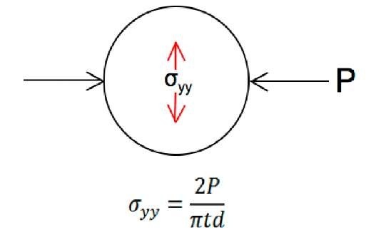
Figure 2 shows the normal equation used to obtain the tensile strength, a, for a diametric compression test.
Figure 2: Compressive loading and tensile stress diagram/equation for diametric compression setup
where P is the axial compressive load, D is the specimen diameter and t is the specimen thickness. A modification to this equation is used in [9] to account for the spreading of the load at the contact points. However, the modified equation introduces a contact width parameter between the sample and the curved loading platens, which is difficult to measure. Thus the modified equation is not used for the work presented here. For a contact width of 2.5mm for a 25mm diameter sample, the stress is only reduced by 4% by the modified equation, so the implication of ignoring this correction factor is relatively small.
Low and intermediate loading rate experiments
The low and intermediate rate diametric compression tests were performed using a 5000lb Instron hydraulic test machine. The tests were conducted with a constant compressive displacement rate of 0.001mm/s for the low rate and 1mm/s for the intermediate rate experiments. Instrumentation for these tests included the load cell and displacement transducer in the test machine and high-speed video to record the material loading and failure process.
High loading rate experiments
The high rate diametric compression tests were performed on a compression Split-Hopkinson Pressure Bar (SHPB) with 1%" diameter aluminum input and output bars. Background on the SHPB and test methodology is provided in [10]. The SHPB input and output bars were instrumented with semiconductor strain gauges. The semiconductor gauges have a much higher sensitivity compared with traditional metal foil strain gauges and are essential for measuring the small strains associated with testing concrete in tension. A comparison of the signals from the two gauge types is shown in figure 3, which illustrates the noise reduction using the higher sensitivity semiconductor gauges.
Figure 3: Comparison of metal foil and semiconductor strain gauges – voltage signal (left); and strain signal (right)
A 24" long striker bar, accelerated by compressed nitrogen, was used to impact the input bar to produce the compressive incident pulse. This was used to load the sample at a compressive displacement rate of approximately 1000mm/s. The striker bar had a flat impact end, however a small amount of silicon grease on the impact face was used for shaping the incident pulse. This has the effect of damping high frequency components (ringing) associated with the impact and increases the pulse rise time to load the specimen more gradually. Ramping the load in this way is critical for allowing time for the stress to equilibrate, through multiple wave reverberations, in the sample. This is particularly important for brittle materials, which only undergo minimal strain before failure and equilibrium needs to be achieved before this time for a valid fracture strength to be reported. Pulse-shaping of the incident pulse for SHPB experiments is discussed further in [11]. Figure 4 shows a detail of the high loading rate experimental setup.
Figure 4: High rate loading experimental setup
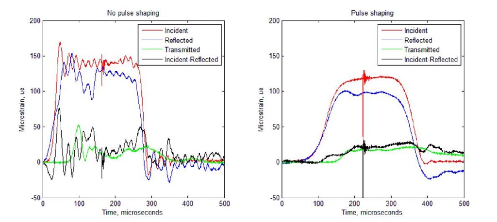
Figure 5 shows experimental results performed here with and without pulse shaping. The shape of the incident pulse is changed significantly and the comparison between the transmitted and incident minus reflected pulses, which is proportional to the force on either side of the sample (ie. the stress equilibrium condition), is greatly improved.
Figure 5: Test with no pulse-shaping (left); and with pulse-shaping using silicon grease (right)
The specimen loading and failure process for the high rate tests was imaged using a Shimadzu Hypervision HPV2 high-speed camera. This camera produces 102 frames at 312×260 resolution at a frame rate of up to 1 million frames per second. The camera was synchronized to the strain gauge on the output bar, so the images could be related to the stress history in the sample from the transmitted pulse. The high-speed images provided a visual assessment that the crack was initiating in the centre of the specimen rather than at the loading contact points.
Tensile strain and strain rate
Using the diametric compression technique it is easy to measure the compressive displacement rate associated with a test. This can be calculated from the reflected pulse for the SHPB high rate tests and is available from the machine displacement transducer for the intermediate and low rate tests. However, in measuring the tensile strength of the material, it is the tensile strain and strain rate, which is of interest. For diametric compression tests, other researchers have instrumented the sample with a strain gauge [8,12] to measure the tensile strain. However, by gluing a strain gauge to the sample where it is expected to fail, this has the potential to reinforce the material and influence the tensile failure strength and crack initiation defect point. Other non-invasive techniques for measuring the tensile strain include full field optical techniques such as moire interferometry [13, 14] and Digital Image Correlation (DIC) [9,13,15,16]. The DIC technique involves high speed imaging of a random speckle pattern (natural or painted) on the specimen surface. The deforming images are correlated spatially at each time step to calculate the sample deformations and strain fields. The DIC technique was attempted here, however, it was found that the strain in concrete before failure was too small to reliably measure displacement fields using this technique. The camera resolution and speckle size were the limiting factors for the strain sensitivity and the background noise. Consequently, it was not possible to measure the tensile strain and strain rate for the diametric compression tests reported here and the rate sensitivity is reported using the stress loading rate instead. The stress loading-rate divided by the quasi-static material elastic modulus has been used by other researchers [12,17] to estimate the tensile strain rate from diametric compression tests. However, this is avoided here due to apprehension in using quasi-static values for the modulus, which may potentially be different under dynamic loading conditions.
High loading rate direct tension tests
The high rate direct tension tests were conducted using a tension SHPB with %" steel input and output bars instrumented with semiconductor strain gauges. The tension SHPB is shown schematically in figure 6. It uses a hollow striker bar which impacts a flange at the end of the input bar to produce the tensile pulse. The samples were glued to detachable platens, which screwed into the input and output bars. The glue used was Sikadur crack fix structural epoxy, which was found to have a high rate bond strength of 20-25MPa when used in this application. This was high enough to successfully test the mortar and SAM35 concrete, however not strong enough for the UHPC and granite. Several tests were attempted for the UHPC, however these resulted in failure at the glue line rather than in the material itself. Figure 7 shows some of the direct tension specimens for mortar, SAM35 and UHPC. Note the very large aggregate size for SAM35 concrete.
Figure 6: Split Hopkinson Pressure Bar schematic for high rate direct tension testing
Figure 7: High rate direct tension specimens
RESULTS
SAM35 concrete
The results for the SAM35 concrete are shown in figure 8. It was tested using the diametric compression technique at low, intermediate and high loading rates and also at high rate in direct tension. The results show significant scatter and this can be attributed to the material in-homogeneity (due to the aggregate components) for the small specimen size used here. The mean tensile strength at low rate (quasi-static loading conditions) was 2.5MPa. This is approximately 10% of the indicated quasi-static compressive strength of 24MPa (3500psi).
Figure 8: SAM35 concrete tensile strength versus loading stress rate
The SAM35 concrete exhibited a strong loading rate effect, with the tensile strength increasing with loading stress rate. This increase was fairly linear over the loading rate range considered here and the mean tensile strength of 5.5MPa at high rate was more than double the low rate (quasi-static) value of 2.5MPa.
The data points for direct tension at high rate are also shown in Figure 8. The comparison between the diametric compression and direct tension test techniques at high rate was very good for this material.
Mortar
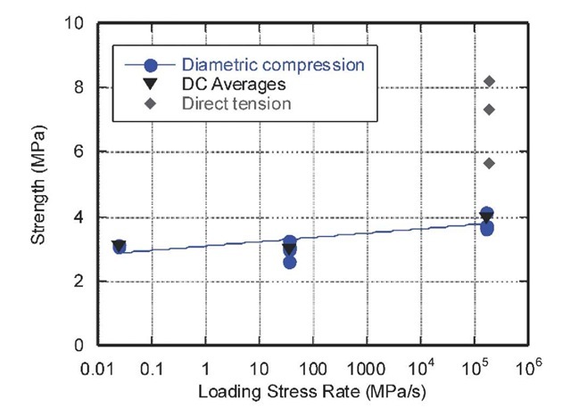
The mortar was also tested at low, intermediate and high loading rates using the diametric compression technique and at high rate in direct tension. These results are shown figure 9. The mortar material is more homogeneous compared with the SAM35 concrete. It still contains sand particles within a cement matrix, however it has no large aggregate components. This resulted in less scatter of the data points for the diametric compression tests. The mean tensile strength at low and intermediate loading rates was approximately the same, 3MPa, and increased to 4MPa at the high loading rate. Thus, the loading rate effect on tensile strength for this material is only evident at the high rate and differs from that seen with the SAM35 concrete.
The comparison between the two test techniques at high rate was poor for the mortar material. The tensile strength measured by the diametric compression technique was significantly lower than that measured by the direct tension tests (although there was significant scatter in the direct tension results). Thus, compared with the SAM35 concrete results, it seems that the agreement between the two test techniques may be material dependent. The direct tension test produces a nominally uniaxial tensile stress state, whereas the diametric compression test produces a more complex biaxial tension-compression stress state as discussed in [5]. Thus it is possible that the SAM35 concrete response is similar under both stress states, whereas the mortar response is different due to different macro and microstructural mechanisms.
Figure 9: Mortar tensile strength versus loading stress rate
The effect on specimen disc thickness for the diametric compression tests was investigated for the mortar. The diametric compression results shown in figure 9 were obtained using disc samples with nominally 20mm diameter (D) and %" (6.35mm) thickness (L), resulting in a cylinder with L/D of approximately 0.3. In comparison, the direct tension tests were performed with cylindrical specimens with an L/D=1 (20mm diameter, 20mm thickness/length). Consequently, the diametric compression tests at high rate were repeated with specimens with an L/D=1 (although in a different orientation to the direct tension tests) and these results are presented in table 1 and figure 10. The tensile strength determined by the diametric compression technique should not depend on the specimen thickness, however, the mean tensile strength increased by approximately 10% using the longer specimens (L/D=1). This is possibly due to inertial material confinement effects. However, despite the small increase, there was still significant disparity with the direct tension results.
Table 1: Mortar high rate tensile strength results – effect of specimen geometry
|
Mortar High Rate Tensile Strength (MPa) |
||
|
Diametric Compression |
Direct Tension |
|
|
L/D~0.3 |
L/D=1 |
L/D=1 |
|
4.1 |
4.7 |
8.2 |
|
3.6 |
4 |
8.2 |
|
4.1 |
4.5 |
5.7 |
|
3.7 |
4 |
7.3 |
|
4.1 |
4.7 |
5.7 |
|
Mean: 3.9 |
Mean: 4.4 |
Mean: 7.0 |
Figure 10: Tensile strength of mortar as a function of specimen L/D and experiment type


