Introduction
Having examined the workings of vision and color, it is now time to look at the other side of the human/display interface: the display itself. While the basic purpose of all displays is the same – to deliver visual information to the user – the means through which this is accomplished varies significantly among the various types and technologies of display devices. Quite often, as we will see, the display technology itself has a significant impact on the appearance of the image, and it is up to the designer of the complete display system to ensure that the appearance is satisfactory and meets the requirements of the application. In this topic, we review some of the basics of the most popular display technologies as well as several new types, along with their unique characteristics and the typical applications and markets for each.
Organizing the various display technologies into a manageable hierarchy may be done in several ways; one such attempt is shown in Figure 4-1. Here, the various display technologies are organized first by whether the fundamental display device produces light – the emissive types – or if it instead functions by modulating externally produced light. However, in a very real and practical sense, the display world divides very neatly into just two categories for many applications: the cathode-ray tube (CRT) display, and everything else. The CRT display, now over 100 years old and still the dominant display technology in almost all nonportable applications, also has some very fundamental differences from practically all of the non-CRT types, and so is reviewed first and receives the lion’s share of attention.
The non-CRT types further divide into subcategories based on their functional properties and the basic technology behind each. However, almost all of these share one characteristic which puts them in sharp contrast with the CRT display: they are typically fixed-format devices, meaning that the display itself comprises a fixed array of independently controllable picture elements, or pixels.
Figure 4-1 A hierarchy of display technologies.
The non-CRT types are often referred to in general as “flat panel displays” (FPDs), since as least most of the direct-view technologies in this category do take that physical form. But this term is becoming less and less applicable as new types, such as the microdisplay, enter the market. A useful breakdown of these types begins with distinguishing whether or not the display device itself emits light (an emissive display), or produces images through controlling the light from an external source. The latter class further divides as we consider where the light source is relative to the display device and viewer, which tells how the display must interact with the light. Thus we have reflective displays (those which control light reflected from the display surface to the viewer), transmissive displays, and some technologies which are capable of operation in either mode. Further categorization in all classes is then by the fundamental operating principle or basic technology used in the construction of the display device.
Despite the very wide range of methods used in creating their images, practically all of the display types to be reviewed here have one basic factor in common: all present spatially twodimensional imagery which is repeatedly transmitted to the display in a regular order. Almost without exception, unless the apparent orientation of the display device with respect to the viewer is altered through optical means.In the typical raster scan, the information corresponding to the extreme upper-left pixel is sent first, and the scan progresses horizontally (to the right) from that point, and then each horizontal row of pixels is transmitted in similar manner from the top of the image to the bottom. There is no inherent advantage to this ordering over any other possible scheme, with the minor exception that progressing along the “long axis”of the display device generally will slightly reduce the transmission rates required. But once this standard was established by early CRT-based devices (and especially television), it remained the norm.
The CRT Display
The origins of the cathode-ray tube, or CRT, stretch back to the late 19th century, and the invention of the electric light bulb by Thomas A. Edison in 1879. In later experiments with this device, it was discovered that a current would pass from the heated filament to a separate plate within the bulb, if that plate was at a positive potential with respect to the filament (the thermionic emission of electrons, originally referred to as the “Edison effect”). Two other discoveries which soon followed paved the way for the CRT as the display we know today: first, in 1897, the German physicist Karl Braun invented what he called an “indicator tube”, based on the recent discovery that certain materials could be made to emit light when struck by the stream of electrons in the Edison-effect bulbs. (Actually, at the time, the electron was not yet known as a unique particle; Braun and others referred to the mechanism that produced this effect as “cathode rays”, thus originating the name for the final display device.) Later, in 1903, the American inventor Lee Deforest showed that the “cathode rays” (the electrons being emitted in these devices) could be controlled by placing a conducting grid between the emitting electrode (the cathode) and the receiving electrode (the anode), and varying the potential on this grid. Combined, these meant that not only could a beam of electrons- the “cathode ray” – be made to produce light, but the intensity of that beam could be varied by a controlling voltage. (DeForest had actually invented the first electronic component capable of the amplification of signals – what in America is called the “vacuum tube”, but which in the UK took the more descriptive name “thermionic valve”.) The modern cathode-ray tube is in essence a highly modified vacuum tube or valve, and is one of the few remaining practical applications of vacuum-tube technology.
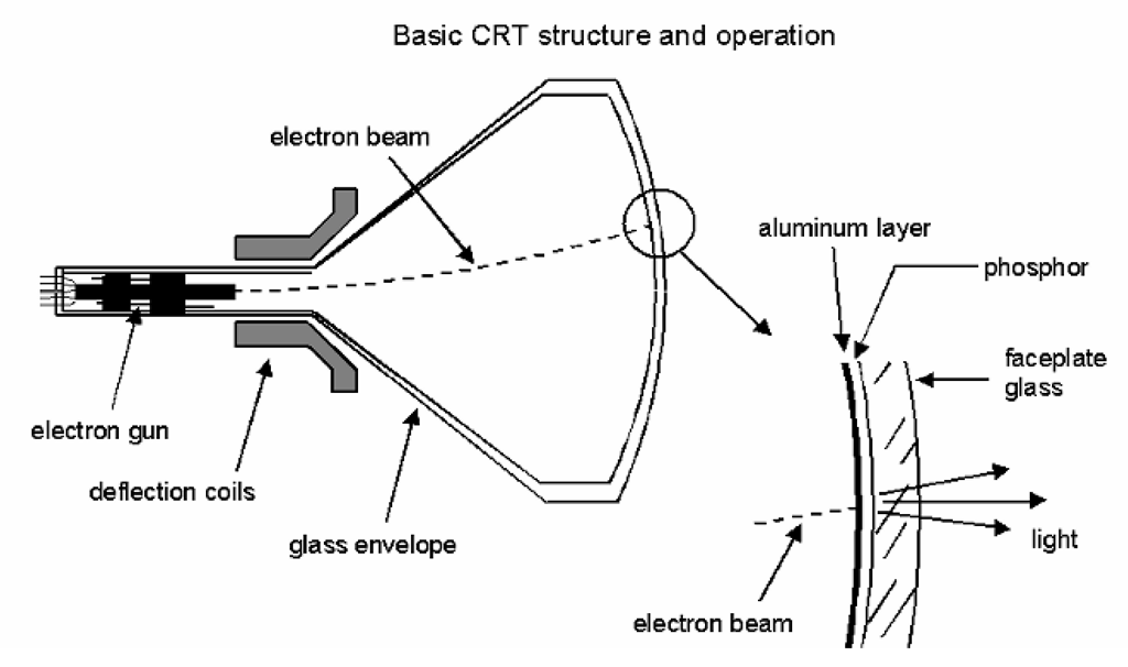
A cross-sectional schematic view of a typical monochrome CRT is shown in Figure 4-2. The cathode, its filament, and the controlling grids and other structures form the electron gun, located in the neck of the tube. The plate, or anode, of the tube is in this case the screen itself, covering the entire intended viewing area (and generally somewhat beyond). This is the first obvious modification from the more typical vacuum-tube structure; the anode is located a considerable distance from the cathode, and is greatly enlarged. This screen structure comprises both the electrical anode of the tube, and the light-emitting surface. Typically, a layer of light-emitting chemicals (the phosphor) is placed on the inner surface of the faceplate glass, and is then covered by a thin, vacuum-deposited metal layer, most often aluminum. The aluminum layer both serves as an electrical contact, and protects the phosphor from direct bombardment by the electron beam. As the light emitted by the phosphor is proportional to the energy transferred from the incoming beam, this stream of electrons must be accelerated to a sufficiently high level. For this reason, the screen is maintained at a very high positive potential with respect to the cathode; usually several thousand volts as an absolute minimum for the smallest tubes, and up to 50 kV or more for the larger sizes. (The screen itself is not adequate to perform the task of accelerating the electrons of the beam; there is almost always an electrode at the anode potential as part of the electron gun structure itself, connected to the screen proper by a layer of conductive material on the inside of the CRT. Therefore, the screen at the face of the tube is more properly referred to as the second anode.)
Figure 4-2 Basic monochrome CRT. In this, the oldest of current electronic display devices, light is produced when a beam of electrons, accelerated by the high potential on the front surface of the tube, strikes a chemical layer (the phosphor). The beam is directed across the screen of the CRT by varying magnetic fields produced by the deflection coils.
In order to be usable as a display device, it is not sufficient that the beam simply impact the screen and cause the phosphor to emit light. The beam must be constrained to produce a small, well-defined spot of light, and some means must be provided for directing that spot and varying its intensity in order to “write” images. Forming a distinct spot from the stream of electrons is achieved through the use of electrodes within the electron gun structure, which produce one or more lenses in the form of shaped electric fields. These work in a manner directly analogous to the action of normal optical lenses on light. To move the resulting spot across the screen, the beam is deflected using magnetic fields. Pairs of coils are mounted on the outside of the tube, around the funnel area, and produce fields which move the beam both horizontally and vertically.One pair of coils – usually those which move the beam along the horizontal axis – scans at a much higher rate than the other, producing the raster pattern as shown. These coils are normally constructed as a single component, referred to as the deflection yoke.
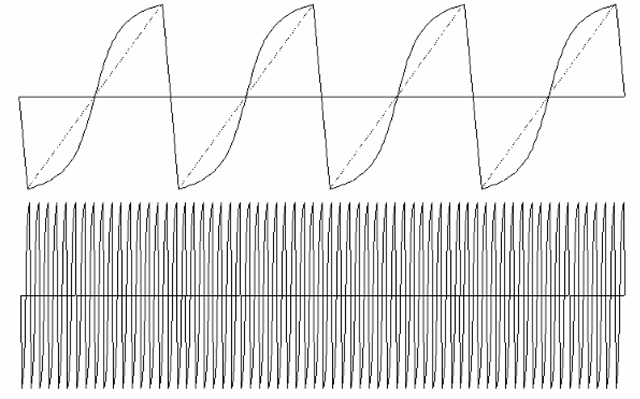
The intensity of the beam, and so the intensity of the light emitted by the phosphor at the screen, is varied by applying a signal corresponding to the desired luminance to the electrodes of the electron gun. Typically, this video signal is applied to the cathode (superimposed on to the DC bias voltage of the cathode), while the “grid” of the tube is tied to a variable DC supply; using cathode drive for a CRT generally results in more stable operation (vs. variations in the anode voltage, etc.). By driving the cathode more negative, the beam current (and so the intensity of the light produced) is increased; therefore, the video signal normally appears “inverted” at this point. The potential difference between the cathode and the fixed grid determines the point at which the beam current goes to zero, also referred to as the “cutoff” or “blanking” point of the CRT. The beam is normally cut off during those portions of the deflection cycle in which the scan is rapidly returned from one side of the tube to the other (or from the bottom of the scan to the top); these are the rapid transitions in the deflection waveform, and are commonly referred to as the retrace periods. The time during which the beam is kept in cutoff, or blanked, must be longer than the actual time required for the retrace, as the deflection coils must be permitted to complete the retrace and stabilize before beginning the next line or frame of the “active” scan.
Figure 4-3 Deflection current waveforms.Note that the waveform has a relatively slow portion, during which the active video is being displayed, followed by a rapid return of the beam to the other side of the screen (the “retrace period”). Also, the waveform in most cases is not a pure “sawtooth” shape (the dotted line in the above figure), but rather is modified into an “S” shape (somewhat exaggerated here for clarity). This compensates for geometric distortion that would otherwise result from the mismatch in the CRT screen radius and the radius of deflection of the electron beam.
This is a greatly simplified description of the operation of a monochrome CRT, but it will suffice for our purposes at this point. Before moving on to the finer details of CRT displays, we next consider how color operation is achieved in this technology.
Color CRTs
The earliest attempts at producing color displays using the CRT employed the field-sequential color technique described in the preceding topic. Separate scans of the fields containing the red, green, and blue components of the color image are displayed in sequence on a CRT with a white phosphor, and viewed through a synchronized color filter wheel. This method can produce a high-quality color image, but is limited by the rate at which the color wheel can operate and its size. Obviously, large-screen color displays using this technique are not practical. (A more recent variant of this technique employs an electrically switched filter panel placed over the CRT, which permits both higher frame rates and larger screen sizes; however, the cost of the filter has restricted its use to only very high-end applications.) Another method of producing color in the CRT, again very seldom used in current designs, is to use a multi-layer phosphor screen, with each layer producing a different color of light. Higher electron-beam energies result in the excitation of more layers of the phosphor, producing a range of output colors. Such beam-penetration color CRTs, however, have a very limited color range, and clearly do not provide a means of varying both the color and the intensity of the light produced. Their use has been restricted to a very small range of industrial applications.
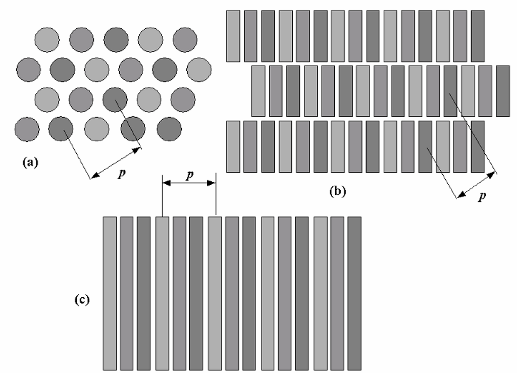
By far the most successful color CRT type is the now-common tricolor “shadow mask” CRT, introduced by RCA in the 1950s as part of their proposed color television system. This basic concept, embodied in a fairly wide range of different tube designs, is used in practically all color CRT displays to this day. In this type of color CRT, the phosphor screen is actually made up of a very large number of discrete dots, stripes, or other patterning of several different phosphors – one for each of the primary colors (typically red, green, and blue) to be produced by the tube. Examples of several different phosphor patterns are shown in Figure 4-4.
Figure 4-4 Color CRT phosphor patterns. The early color CRTs used three electron guns arranged in a triangle in the neck, and the phosphors of these “delta-gun” tubes were also arranged in triangular patterns (a). Later tubes, including most current designs, placed the three guns in a horizontal line, and the “in-line” types use a pattern of rectangular holes as shown in (b). Sony Corp. pioneered a different form of mask, in which the beams were isolated via a grille of flat metal strips under tension; the “ap-erture-grille” types, including Sony’s own Trinitron™ tubes, employ a distinctive phosphor arrangement of continuous vertical stripes. In all types, the phosphor “dot pitch” (p in the above drawings) is defined as the center-to-center distance between adjacent phosphors of the same color; this measurement imposes a fundamental limitation on the resolution capabilities of the tube. However, note that the pitch is measured along a diagonal in the conventional shadow-mask types, and along the horizontal in the aperture-grille types, leading to figures that are not directly comparable in terms of their implied resolution limits.
The electron gun structure is also tripled – three individually controlled beams are produced and directed at the phosphor screen. In order to properly generate a full-color image, however, it should be apparent that each beam should be allowed to excite only one of the three phosphors, thus giving us in effect three independent displays in one – three images, one in each of the primary colors, which are overlaid in a single image area.
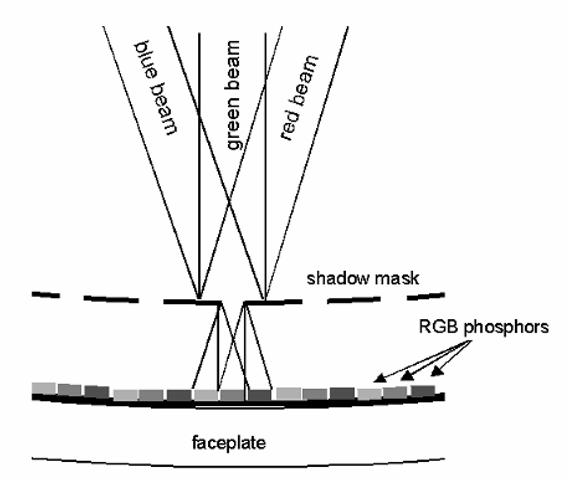
The task of keeping the beams, and therefore the images, separated falls to a structure called the shadow mask. This mask is built into the CRT, located just behind the phosphor screen (and generally mounted onto the faceplate glass). Constructed of metal (originally iron or steel, but today more commonly an alloy with a lower coefficient of thermal expansion), the mask has numerous holes through which the beams can pass. In fact, there is one hole for each set of three phosphor dots on the screen; with the mask so close to the screen, however, only one dot is “visible” to any beam through the mask holes, depending on the angle at which the beam strikes the mask (Figure 4-5). By varying the relative angles at which the three beams strike the mask, then, each beam can be made to excite only the phosphor dots of the correct color, and the others are blocked or “shaded” from that beam by the shadow mask. This method of color separation comes at a price, however; the mask intercepts a high percentage of the beam current (up to 80% or even higher in some designs), and so this type of color CRT requires considerably higher beam energies – and so higher anode voltages – than a similar-sized monochrome tube, in order to provide comparable brightness.
This system clearly requires some fairly sophisticated control of the beam position and trajectory, but nevertheless gave us the first truly practical full-color CRT display. The three beams must be made to strike the same area at the same time, throughout the scanning process, so that only a single spot of the proper color is perceived by the viewer. This is referred to as the convergence of the beams, and the failure to bring the beams together at all times results in misconvergence, the appearance of primary-colored “fringes” around areas of otherwise correct color, or the visible “breakup” of fine details – such as thin lines – into three distinct primary-color images. Even if the beams come together at the proper point, it is still possible that they will not be properly separated by the mask, and one or more beams will then illuminate phosphor of the wrong color.
Figure 4-5 The action of the shadow mask. In a tricolor CRT, the shadow mask acts to separate the effects of the three electron beams on the phosphor dots of the screen. Each beam is made to intercept the mask at a slightly different angle, and so the holes of the mask expose only the desired color of phosphor to a given beam. This diagram is somewhat simplified, and not to scale; for one thing, the electron beams are typically larger in diameter than shown here, such that each may illuminate multiple phosphor dots of that color simultaneously.
This is referred to as a beam mislanding or color purity error, and results in areas of incorrect color being produced. Common problems which can result in this form of error include unwanted magnetic fields, either externally produced or resulting from the buildup of magnetism in the mask or other portions of the display, and/or the physical distortion or shift in location of the mask itself. Mask distortion due to heat is a very common source of beam mislanding; as mentioned above, the mask intercepts much of the energy of the electron beams, and so is prone to heating from this source. Localized expansion of the mask, as might occur when the image has a small, isolated area of high brightness, results in a problem called doming; this is what caused CRT manufacturers to switch to mask materials which have less thermal expansion, or to use other means of better controlling the position of the mask surface.
One such solution was pioneered by Sony Corp. in the 1960s. Instead of a conventional shadow mask, the Sony “Trinitron™” CRT uses an array of flat metal strips or wires, held under tension by a metal frame (the strips run vertically as seen by the viewer of the CRT). The slots between these strips act in the same manner as the holes in a conventional mask, this time with phosphors patterned in continuous stripes. This type of mask structure was named an “aperture grille” by Sony, to distinguish it from the conventional shadow mask, and for many years was unique to Sony tubes. (The aperture grille design has since been licensed to other manufacturers, notably Mitsubishi.) This design results in two visible distinguishing features for the aperture grille tubes. First, since the grille is under tension vertically, the faceplate may be made flat (or nearly so) along this axis, resulting in a cylindrical shape for the screen. Second, the individual strips of the aperture grille would, if not restrained, be subject to vibration and possible damage if the tube were subjected to mechanical shock. To prevent this, very thin damper wires are welded to the aperture grille, running horizontally across the strips. Since these wires do block a small amount of the beams, they are visible are very faint horizontal lines across the image. (Smaller tubes may have only one wire, while the larger ones generally have two.) At normal viewing distances and with most image content – large white areas are obviously the worst case – these artifacts are generally ignorable.


