Clipping
In the last section we showed how to transform the clipping problem to a problem of clipping against the unit cube in clip space. The actual clipping against the cube will be done in homogeneous clip space using homogeneous coordinates (x,y,z,w). The advantage of homogeneous coordinates was already alluded to: every point of camera space is sent to a well-defined point here because values become undefined only when we try to map down to clip space by dividing by w, which may be zero.
These have their place, but they are not geared to geometric modeling environments where one often wants to draw connected segments. We shall now describe a very efficient clipping algorithm for such a setting that comes from [Blin91a]. It uses the “best” parts of the Cohen-Sutherland, Cyrus-Beck, and Liang-Barsky algorithms.
In homogeneous coordinates halfplanes can be defined as a set of points that have a nonnegative dot product with a fixed vector. For example, the halfplane![]()
![]() is defined by the vector (a,b,c,d) in homogeneous coordinates. Therefore, by lining up vectors appropriately, any convex region bounded by planes can be defined as the set of points that have nonnegative dot products with a fixed finite set of vectors. In our case, we can use the following vectors for the six bounding planes
is defined by the vector (a,b,c,d) in homogeneous coordinates. Therefore, by lining up vectors appropriately, any convex region bounded by planes can be defined as the set of points that have nonnegative dot products with a fixed finite set of vectors. In our case, we can use the following vectors for the six bounding planes
If![]() We shall call the BCi the boundary coordinates of p. These coordinates are easy to compute:
We shall call the BCi the boundary coordinates of p. These coordinates are easy to compute:
A point will be inside the clip volume if and only if all of its boundary coordinates are nonnegative. If the ith boundary coordinate of a point is nonnegative, then we shall callthe point i-inside; otherwise, it is i-out. Let![]()
![tmpc646588_thumb[2][2] tmpc646588_thumb[2][2]](http://what-when-how.com/wp-content/uploads/2012/06/tmpc646588_thumb22_thumb.png) denote the vector of boundary coordinates.
denote the vector of boundary coordinates.
Next, let![]() be two points and set
be two points and set![]() The next table shows the relationship of the segment
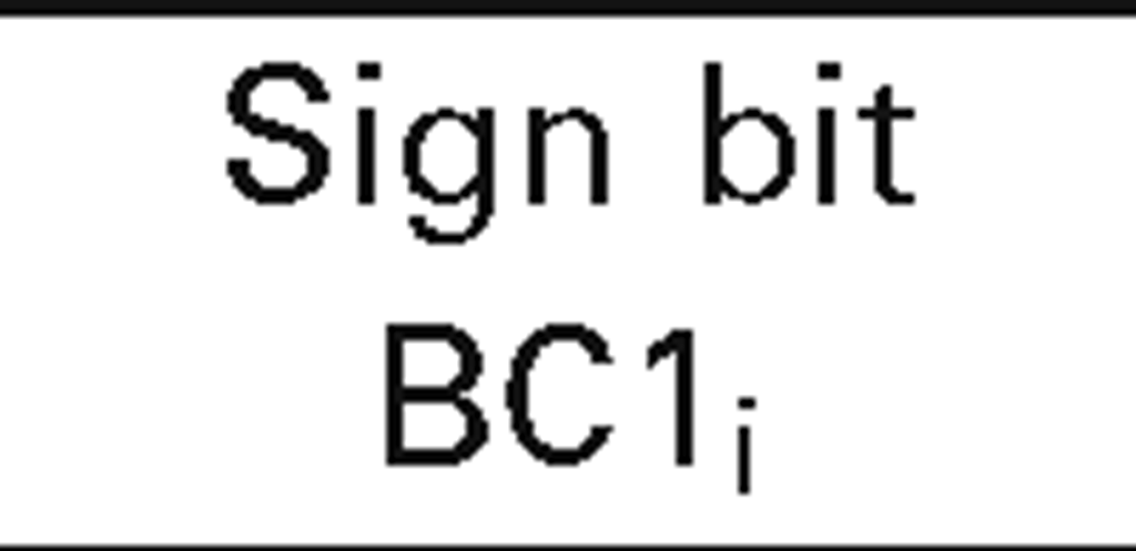
The next table shows the relationship of the segment![]() with respect to the ith boundary:
with respect to the ith boundary:
 |
 |
Meaning |
|
0 |
0 |
Entire segment is i-inside |
|
1 |
0 |
Segment straddles boundary, p0 is i-out |
|
0 |
1 |
Segment straddles boundary, pi is i-out |
|
1 |
1 |
Entire segment is i-out |
It will be convenient to record the sign information of a point p into a six-bit word called its outcode and denote it by CODE(p). More precisely, the ith bit of CODE(p) will be the sign bit of BQ(p). Let CODE0 = CODE(pO) and CODE1 = CODE(p1). Simple logical operations on CODE0 and CODE1 now give us a lot of information about the location of the segment. For example, the segment will be inside the clip volume if (CODE0 or CODE1) is zero. The segment will be entirely outside the clip volume if (CODE0 and CODE1) is nonzero. (Compare this with the Cohen-Sutherland clipping algorithm.)
Whenever the segment crosses the ith clipping plane, we need to find the intersection. This is easy to do if we parameterize the segment, and we have done this sort of thing before. We need to find the t so that
With our notation,![tmpc646600_thumb[2][2] tmpc646600_thumb[2][2]](http://what-when-how.com/wp-content/uploads/2012/06/tmpc646600_thumb22_thumb.png) The segment will intersect the plane only if this t lies in [0,1]. The expression shows that this can only happen if BC0j and BC1j have different signs.
The segment will intersect the plane only if this t lies in [0,1]. The expression shows that this can only happen if BC0j and BC1j have different signs.
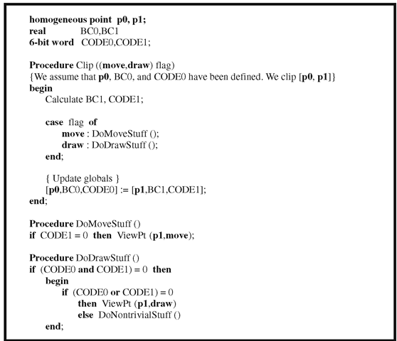
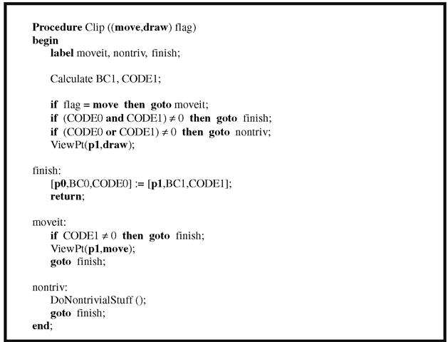
Now, the clipping algorithm we are in the process of describing is intended for situations where we want to do a sequence of “DrawTo” and “MoveTo” commands. The flag parameter in the “Clip” procedure is used to distinguish between the two cases and will save us having to write a separate “Clip” procedure for both. The abstract programs are given in Algorithm 4.6.1 with the ViewPt procedure representing the next stage of the graphics pipeline after clipping, namely, the clip-space-to-pixel-space map. A more efficient procedure using goto’s, assuming that the trivial rejects are the most common cases, is shown in Algorithm 4.6.2.
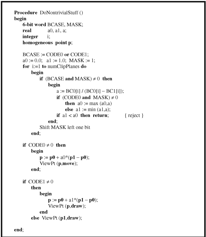
Next, we describe the nontrivial stuff that happens when a segment straddles a boundary. We basically use the Liang-Barsky algorithm here. In Algorithm 4.6.3, the variables a0 and a1 keep track of the still-visible part of a segment. MASK is used to select one boundary at a time. Blinn points out that he does the operation CODE0 or CODE1 again on the theory that it will not get done often and we save storing an unneeded value earlier. He also made all tests as much as possible into integer comparisons to cut down on floating point operations.
Algorithm 4.6.1. Abstract programs for clipping using homogeneous coordinates.
There are some limitations to Blinn’s clipping algorithm. Although they tend to be more theoretical than practical, one should be aware of them. The problem is that one is clipping to the infinite inverted pyramid in homogeneous coordinate space shown in Figure 4.12(a) when, in fact, one should be clipping to the double pyramid shown in Figure 4.12(b). The points in the negative pyramid will also project to the visible region. On the other hand, the basic graphics pipeline that we have been describing will not introduce any negative w’s and so this problem will not arise here. The problem arises only if negative w-coordinates are introduced explicitly or if one wants to represent infinite segments (the complement of a normal segment in a line). If one does want to handle such cases, the quickest way to do it is to draw the world twice, once as described above and then a second time, where the matrix that maps from shape to clip coordinates is multiplied by -1.
Algorithm 4.6.2. More efficient clipping using homogeneous coordinates.
Figure 4.12. Single- and double-clip pyramid.
Algorithm 4.6.3. The nontrivial part of homogeneous coordinate clipping.
Putting It All Together
We are finally ready to put all the pieces together. See Figure 4.1 again.Starting with some shape we are initially in shape coordinates. We then
(1) transform to world coordinates
(2) transform from world to homogeneous clip coordinates by composing
(4) project (x,y,z,w) down to (x/w,y/w,z/w) in the unit cube of clip space with Tproj
(5) map the unit square in the x-y plane of clip space to the viewport
(6) map from the viewport to pixel space
With respect to (4), note that using a front clipping plane does have the advantage that we do not have to worry about a division by zero. Almost, but not quite. There is the very special case of (0,0,0,0) that could occur and hence one needs to check for it (Exercise 4.7.1). It would be complicated to eliminate this case.
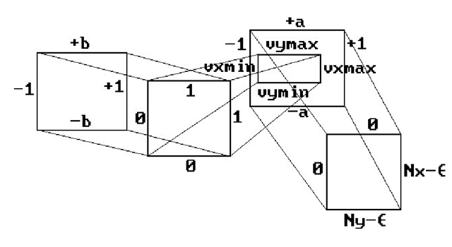
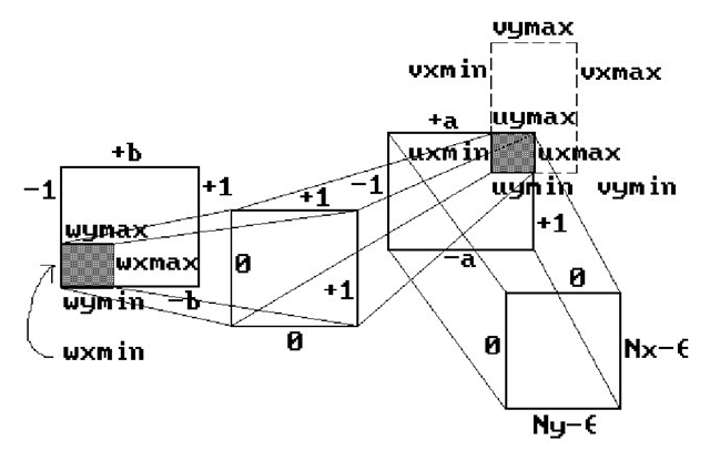
Also, because of the clipping step, Blinn suggests a more complete version of the window-to-pixel map than shown in Figure 4.9. See Figure 4.13. The square [0,1] x [0,1] represents the clipping. This allows one to handle the situation shown in Figure 4.14, where the viewport goes outside the valid NDC range quite easily. One pulls back the clipped viewport
and then uses that rectangle as the window. Only the transformation Tcam^hciip needs to be changed, not the clipping algorithm.
Blinn’s approach is nice, but there may not be any need for this generality. A much simpler scheme that works quite well is to forget about the NDC by incorporating the hardware aspect ratio rh into the window size. Let
be the current viewport. Then fix the window to be the rectangle [-1,1] x [-b,b], where
Figure 4.13. From window to pixel coordinates.
Figure 4.14. General window and viewport example.
Now map directly from [0,1] x [0,1] to pixel space. With this window and the view transformations discussed in this topic, circles will look like circles.
We close with a final remark on clipping. Clipping is expensive and therefore we would rather not do it! In future topics we shall discuss ways one can often avoid it (by using bounding boxes, the convex hull property of splines, etc.).
Stereo Views
Occasionally, it is useful to allow the origin of the view plane to be a point other than the one directly in front of the camera. One such case is where one wants to compute stereo views. This involves computing two views, one for each eye.
The Eye Coordinate System. Given a camera, let![]() _ j be the camera coordinate system, where the vectors
_ j be the camera coordinate system, where the vectors![]() are defined by equation (4.1) If we think of one eye as being located at
are defined by equation (4.1) If we think of one eye as being located at![]() then the eye coordinate system with respect to the given camera and some
then the eye coordinate system with respect to the given camera and some![]() is defined by the frame
is defined by the frame
![]() If
If![]() then this is the same as the camera coordinate system.
then this is the same as the camera coordinate system.
It is easy to see that if the coordinates of a point p in camera coordinates is (x,y,z), then the coordinates of that same point in eye coordinates are![]() Furthermore, if p projects to (x’,y’,d) in eye coordinates, then it projects to
Furthermore, if p projects to (x’,y’,d) in eye coordinates, then it projects to![]() b,d) in camera coordinates. It follows that, using homogeneous coordinates, the only difference in computing the view in camera coordinates to computing it in eye coordinates amounts to replacing the matrix
b,d) in camera coordinates. It follows that, using homogeneous coordinates, the only difference in computing the view in camera coordinates to computing it in eye coordinates amounts to replacing the matrix![tmpc646621_thumb[2][2] tmpc646621_thumb[2][2]](http://what-when-how.com/wp-content/uploads/2012/06/tmpc646621_thumb22_thumb.png) in equation (4.9) by
in equation (4.9) by
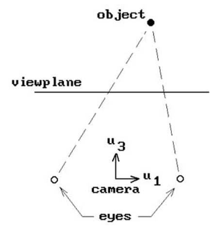
Figure 4.15. Views from two eyes for stereo.
To compute stereo views one would compute two views – one with the eye at p + au1 and one with the eye at p – au1 for some suitable a. See Figure 4.15. The two views are then displayed a suitable distance apart in a viewport. Actually, our discussion here is a simplification of what is involved in stereo rendering and we refer the reader to [Hodg92] for a much more thorough overview.
![tmpc646583_thumb[2][2] tmpc646583_thumb[2][2]](http://what-when-how.com/wp-content/uploads/2012/06/tmpc646583_thumb22_thumb.png)
![tmpc646586_thumb[2][2] tmpc646586_thumb[2][2]](http://what-when-how.com/wp-content/uploads/2012/06/tmpc646586_thumb22_thumb.png)
![tmpc646599_thumb[2][2] tmpc646599_thumb[2][2]](http://what-when-how.com/wp-content/uploads/2012/06/tmpc646599_thumb22_thumb.png)

![tmpc646606_thumb[2][2] tmpc646606_thumb[2][2]](http://what-when-how.com/wp-content/uploads/2012/06/tmpc646606_thumb22_thumb.png)
![tmpc646608_thumb[2][2] tmpc646608_thumb[2][2]](http://what-when-how.com/wp-content/uploads/2012/06/tmpc646608_thumb22_thumb.png)
![tmpc646632_thumb[2][2] tmpc646632_thumb[2][2]](http://what-when-how.com/wp-content/uploads/2012/06/tmpc646632_thumb22_thumb.png)
