Choosing the Coordinates of a Pixel
Before going on to discuss another scan conversion algorithm we pause to take up a subject that probably did not occur to the reader as being an issue. However, since pixels should be treated as having area, if we consider our image as corresponding to a grid as we have, where should the pixels be placed? Should they be at the intersection of the grid lines or in the center of the grid squares? Equivalently, when we consider scan lines, do their y-coordinates fall on integers or half-integers? Whatever choice one makes, it does matter. We summarize the conclusions of the excellent article by Heckbert [Heck90a].
The real issue here is how one maps reals to integers. Should one round or truncate? Rounding corresponds to placing pixels at the integers because the whole interval [n - 0.5,n + 0.5) will map to n. Truncating corresponds to placing the pixels at half-integers because the whole interval [n,n + 1) will map to n. To use an example, if one rounds, then the interval [-.5,2.5) maps to [0,1,2], whereas if one truncates, then [0,3) maps to [0,1,2]. The second approach is a cleaner choice because there are no .5′s to worry about. By truncating one simplifies some mathematics. We shall therefore use the following correspondence if we need to map back and forth between the continuous and discrete world:
(Mathematically it is the Floor function that returns an integer whereas the Trunc function returns a real.) In two dimensions this means that when we have a pixel with coordinates (x,y), its center will be at continuous coordinates![tmpc646-160_thumb[2][2][2] tmpc646-160_thumb[2][2][2]](http://what-when-how.com/wp-content/uploads/2012/06/tmpc646160_thumb222_thumb.png) Note
Note
that this was the choice we made when discussing antialiasing. Now we know why.
In the future, whenever we scan a continuous object the scan lines will fall on half-integers.
More Drawing Algorithms
Scan Converting Polygons
The Bresenham line-drawing algorithm discussed in Section 2.5.2 dealt with scan converting a single segment. There may be several segments we want to scan convert such as the boundary of a polygon. In that case one can use the coherence inherent in that problem and use an algorithm that is more efficient that simply scan converting each bounding edge separately.
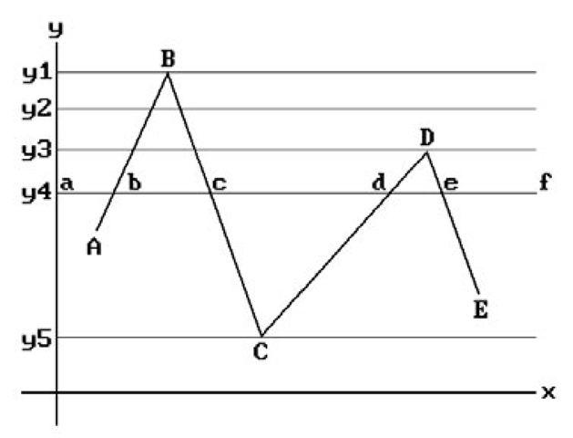
Consider the edges in Figure 2.16. As we move down from the top of the picture one scan line at a time we do not need to compute the intersections of the edges with the scan line each time. These can be computed incrementally. Since not every edge will intersect current scan line, by using an active edge list (AEL), we do not have to look at every edge each time. Here are the steps to scan convert these edges efficiently:
Figure 2.16. Scan converting a polygon.
Step 1. Associate a “bucket” to each scan line and initialize it to empty.
Step 2. Find the largest y value for each edge and put the edge into the corresponding scan line’s bucket.
Step 3. For each edge e maintain the following information:
x – initially the x-coordinate of the highest point of the edge e (in general the x-coordinate xe of the intersection of e with the current scan line) dx – change in x from line to line (the reciprocal of the slope of the line) dy – initially the number of scan lines crossed by e
Step 4. Initialize the active edge list to empty. Set y to the height of the top scan line. Step 5. Add any edges in the bucket for y to the active edge list.
Step 6. For each edge in the active edge list draw (x,y), change the x to x + dx, and decrement dy. If dy becomes 0, then remove that edge from the list.
Step 7. Decrement y. If y is 0, then quit; otherwise, go back to Step 5.
In Figure 2.16, when we reach scan line y1, the edges AB and BC will be added to the active edge list. At scan line y2 nothing special happens. When we get to scan line y3, the edges CD and DE will be added to the list. Finally, at scan line y5 there are only the two edges BC and CD on the list and they will now be removed.
To avoid having fixed bucket sizes and limiting the amount of data for each scan line, one stores pointers only and stores all information sequentially in an array. Alternatively, one can use a linked list to be able to add and delete easily.
A problem related to scan converting lists of edges which is of more practical importance is scan converting solid polygons. This leads to polygon based fill algorithms. The pixel-based analog was already discussed earlier in Section 2.4.
Assume that XMIN, XMAX, YMIN, and YMAX are the minimum and maximum values for the x- and y-coordinates of pixels. The basic idea here is the following:
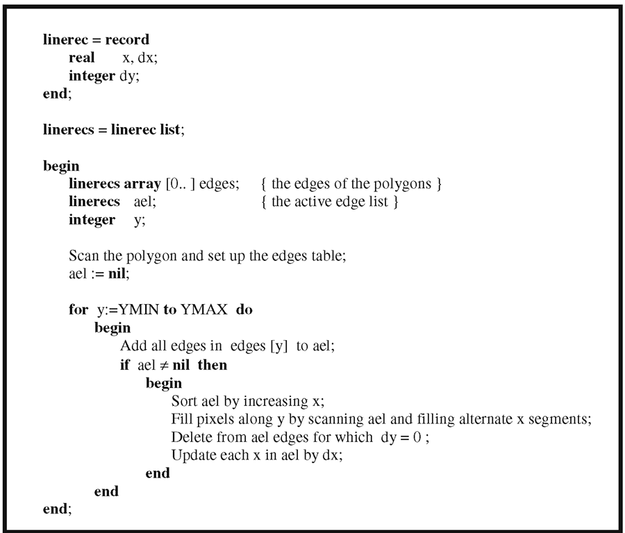
The Boolean-valued function “Inside” counts the intersections of the line from (j,i) to ![]() with the polygon. If this number is odd, then the function returns true, other- wise it returns false. Of course, this algorithm is too slow. One needs to take scan line coherence into account. This leads us to what are called ordered edge list fill algorithms. They have the following general form:
with the polygon. If this number is odd, then the function returns true, other- wise it returns false. Of course, this algorithm is too slow. One needs to take scan line coherence into account. This leads us to what are called ordered edge list fill algorithms. They have the following general form:
For example, consider the scan line y4 in Figure 2.16. Notice how filling the alternate segments [b,c] and [d,e] does in fact fill what we want. That this works is justified by a parity type argument. An active edge list again helps. Algorithm 2.9.1.1 shows a more detailed version.
Algorithm 2.9.1.1. An ordered edge list fill algorithm.
The following points need to be made about Algorithm 2.9.1.1:
(1) The polygon is assumed to lie entirely in window.
(2) Horizontal edges need not be considered because they get filled automatically.
(3) There is a problem with parity at vertices unless one takes precautions.
To understand the parity problem at vertices consider Figure 2.16 again. At vertices, their x values would be listed twice in the active edge list. In the case of a local maximum like vertex![]() the algorithm would fill the segments
the algorithm would fill the segments![]()
![]() on the scan line
on the scan line![]() to the background color, the color of the polygon, and the background color, respectively. This is as we would want it. On the other hand, when the algorithm gets to vertex
to the background color, the color of the polygon, and the background color, respectively. This is as we would want it. On the other hand, when the algorithm gets to vertex![]() assuming that there was another edge below this vertex, it would fill
assuming that there was another edge below this vertex, it would fill![]() to the background color,
to the background color,
![]() to the color of the polygon, and
to the color of the polygon, and![]() to the background color, etc. This
to the background color, etc. This
is not correct. Furthermore, we cannot simply skip duplicate x-coordinates as we scan the active edge list. If we did, then vertices like A would be handled correctly, but the algorithm would now fail at local maxima and minima like B. The way that this parity problem is usually resolved is to shorten one of the (two) edges that meet in a vertex that is not at a local extremum. For example, change the lower vertex (x,y) of the upper edge to![tmpc646-176_thumb[2][2][2] tmpc646-176_thumb[2][2][2]](http://what-when-how.com/wp-content/uploads/2012/06/tmpc646176_thumb222_thumb.png) (leaving the upper vertex of the lower edge in tact). No shortening takes place at vertices that are local extrema. With this change to the edges, Algorithm 2.9.1.1 will now work correctly, but we need a test for when vertices are local extrema. Here is one:
(leaving the upper vertex of the lower edge in tact). No shortening takes place at vertices that are local extrema. With this change to the edges, Algorithm 2.9.1.1 will now work correctly, but we need a test for when vertices are local extrema. Here is one:
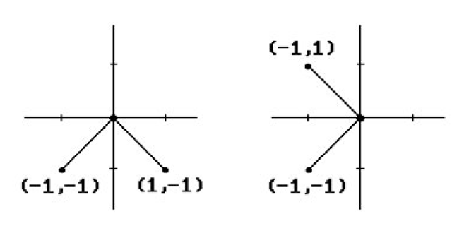
To see that a further test is required in the else case, consider Figure 2.17 and the two pairs of segments ([(-1,-1),(0,0)],[(0,0),(1,-1)]) and ([(-1,-1),(0,0)],[(0,0),(-1,1)]). In both pairs, the segments have opposite slopes, but (0,0) is a local extremum for the first pair but not for the second. One can tell the two apart however because the endpoints (-1,-1) and (-1,1) for the first pair lie on opposite sides of the scan line for (0,0), whereas the endpoints (-1,-1) and (1,-1) both lie on the same side of the scan line.
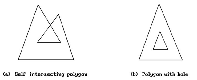
Finally, note that the ordered edge list fill algorithm “works” for polygons with self-intersections and/or holes. See Figure 2.18. One needs to understand what “works” means though.
Figure 2.17. Testing for local extrema.
Figure 2.18. Various types of polygon.
For example, the inside of the inner loop of Figure 2.18(a) will be drawn in the background color.
In the algorithm above, as we go along we must now keep track of the polygon to which the “current” segment “belongs.” One way to do this is to maintain the following additional data:
(1) covers – a Boolean array so that covers[i] is true for the ith polygon if it covers the current segment
(2) numcover – the number of polygons covering the current segment
(3) visiblePoly – a pointer to the foremost polygon, if any
As we move from segment to segment in a scan line, numcover is incremented or decremented appropriately. The array covers is initialized to false and every time that one runs into an edge of the ith polygon, covers[i] is negated. The pointer visiblePoly tells us the color of the current segment.
In conclusion, here are some points to consider when deciding on a fill algorithm. The main advantages of ordered edge list algorithms are that pixels are visited only once and they are well suited for shading algorithms since both ends of a span are computed before the span is drawn so that one can interpolate intensities. The main disadvantage is the large amount of processing required maintaining and sorting various lists. The main advantage to seed fill algorithms is that they can fill arbitrary planar contours, not just those bounded by polygonal curves. The main disadvantages are that some pixels are visited many times and one requires an initial interior point. The latter is not a problem in interactive situations but would be in a fully automated one. One would then have to invoke another algorithm to find such a point. See [AckW81] for some conclusions based on performance tests. Basically, fill time tends to be dominated by the time required to set pixels making the ordered edge list algorithms the most attractive overall. [FisB85] compares various specific seed fill algorithms. An antialiased scan conversion algorithm is described in [Morr90].
Drawing Circles
Probably the most straightforward approach to generating points on a circle is to use a polar coordinate parameterization. If, for simplicity, we restrict the discussion to circles of radius r centered at the origin, then this map is given by the formula
The only problem with this is that the sine and cosine functions are relatively complicated to evaluate. We want a speedier algorithm. One can use rational functions. For example, there is the following rational function parameterization of the right half of the unit circle
These rational polynomials can be evaluated rather efficiently using a method of forward differences, but the problem now is that equally spaced t’s do not give rise to equally spaced points on the circle.
The DDA approach that led to a good algorithm in the case of lines is also applicable to circles. By differentiating the equation
for a circle of radius r about the origin implicitly with respect to x, one sees that
is the differential equation for that circle. This means that a circle-generating DDA can be written in the form
A natural choice for e is![tmpc646-194_thumb[2][2][2] tmpc646-194_thumb[2][2][2]](http://what-when-how.com/wp-content/uploads/2012/06/tmpc646194_thumb222_thumb.png) Unfortunately, if one were to plot the points that are generated by these equations, one would find that they spiral outward. From a mathematical standpoint one should not have been surprised because the determinant of the matrix
Unfortunately, if one were to plot the points that are generated by these equations, one would find that they spiral outward. From a mathematical standpoint one should not have been surprised because the determinant of the matrix
for this linear transformation is![]() An ad hoc way to correct this determinant problem is to make a slight change and note that the matrix
An ad hoc way to correct this determinant problem is to make a slight change and note that the matrix
has determinant equal to 1. The points that are generated by the corresponding transformation produce a much better result. The equations for this transformation are
which reduces to
Notice how the equation for the (n + 1)st value for y now also involves the (n + 1)st value of x. The coordinates of the new point have to be computed sequentially, first the x value, then the y value. Before we could compute them in parallel. Furthermore, what we have here is a simple example of an error-correcting term. All good methods for numerical solutions to differential equations have this, something that was alluded to in Section 2.5.1.
Returning to our problem of generating points on a circle, our new system of equations produces points that no longer spiral out. However, having determinant equal to 1 is only a necessary requirement for a transformation to preserve distance. It is not a sufficient one. In fact, the points generated by our new transformation form a slight ellipse.
To get a better circle-generating algorithm we start over from scratch with a new approach. Assume that the radius r is an integer and define the “error” function E by
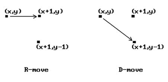
This function measures how close the point (x,y) is to lying on the circle of radius r. As we generate points on the circle we obviously want to minimize this error. Let us restrict ourselvesto the octant of the circle in the first quadrant, which starts at (0,r) and ends at![]() Note that in this octant as we move from one point to the next the x-coordinate will always increase by 1 and the y-coordinate will either stay the same or decrease by 1. Any other choice would not minimize E. The two cases are illustrated in Figure 2.19. We shall call the two possible moves an R-move or a D -move, respectively.
Note that in this octant as we move from one point to the next the x-coordinate will always increase by 1 and the y-coordinate will either stay the same or decrease by 1. Any other choice would not minimize E. The two cases are illustrated in Figure 2.19. We shall call the two possible moves an R-move or a D -move, respectively.
As we move from point to point, we choose that new point which minimizes E. However, we can save computation time by computing the new E incrementally. To see this, suppose that we are at (x,y). Then the current![]() is given by
is given by
Figure 2.19. Moves in circle-generating algorithm.
After an R-move the new E, call it ER, is
After a D-move the new E, call it ED, is
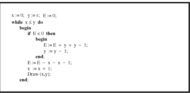
One algorithm for drawing a circle is to choose that move which makes our new error, either![tmpc646-211_thumb[2][2][2] tmpc646-211_thumb[2][2][2]](http://what-when-how.com/wp-content/uploads/2012/06/tmpc646211_thumb222_thumb.png) have the opposite sign of our current one. The idea is that if we find ourselves outside the circle we should move as quickly as possible back into the circle and vice versa. This leads to Algorithm 2.9.2.1, the Bresenham circle-drawing algorithm.
have the opposite sign of our current one. The idea is that if we find ourselves outside the circle we should move as quickly as possible back into the circle and vice versa. This leads to Algorithm 2.9.2.1, the Bresenham circle-drawing algorithm.
The only problem with Algorithm 2.9.2.1 is that we were using a heuristic that does not always minimize the real error E (Exercise 2.9.2.1). To get a better algorithm, we have to make that our goal. Choosing the move that minimizes the error can be done by testing the sign of![]() To gain efficiency we want to avoid having to compute absolute values of numbers. Consider the possible outcomes shown in following table:
To gain efficiency we want to avoid having to compute absolute values of numbers. Consider the possible outcomes shown in following table:
Algorithm 2.9.2.1. The Bresenham circle-drawing algorithm (one octant).
This table shows that the sign of![tmpc646-217_thumb[2][2][2] tmpc646-217_thumb[2][2][2]](http://what-when-how.com/wp-content/uploads/2012/06/tmpc646217_thumb222_thumb.png) always agrees with the sign of the auxiliary variable
always agrees with the sign of the auxiliary variable
Furthermore, G can also be computed incrementally. Let GR and GD denote the values of G after an R-move or D-move, respectively. If![]() is the current G value, then
is the current G value, then
and
It is easy to derive formulas (2.4) and (2.5). We prove formula (2.4) for GR in case we move right. Recall that
On an R-move,
The other cases are proved in a similar fashion.
Finally, going one step further, the increments to GR and GD themselves can be computed incrementally, producing an improved Algorithm 2.9.2.2. It can be shown that the algorithm produces a best-fit curve for the circle when either the radius r or its square is an integer, but that may not be the case if one tries the same approach when r2 is not an integer.
See [Blin87] for a more complete overview of circle drawing algorithms. For a version of the midpoint line-drawing algorithm that works for circles see [VanN85].
![tmpc646-159_thumb[2][2][2] tmpc646-159_thumb[2][2][2]](http://what-when-how.com/wp-content/uploads/2012/06/tmpc646159_thumb222_thumb.png)
![tmpc646-161_thumb[2][2][2] tmpc646-161_thumb[2][2][2]](http://what-when-how.com/wp-content/uploads/2012/06/tmpc646161_thumb222_thumb.png)
![tmpc646-163_thumb[2][2][2] tmpc646-163_thumb[2][2][2]](http://what-when-how.com/wp-content/uploads/2012/06/tmpc646163_thumb222_thumb.png)
![tmpc646-166_thumb[2][2][2] tmpc646-166_thumb[2][2][2]](http://what-when-how.com/wp-content/uploads/2012/06/tmpc646166_thumb222_thumb.png)
![tmpc646-186_thumb[2][2][2] tmpc646-186_thumb[2][2][2]](http://what-when-how.com/wp-content/uploads/2012/06/tmpc646186_thumb222_thumb.png)
![tmpc646-189_thumb[2][2][2] tmpc646-189_thumb[2][2][2]](http://what-when-how.com/wp-content/uploads/2012/06/tmpc646189_thumb222_thumb.png)
![tmpc646-190_thumb[2][2][2] tmpc646-190_thumb[2][2][2]](http://what-when-how.com/wp-content/uploads/2012/06/tmpc646190_thumb222_thumb.png)
![tmpc646-191_thumb[2][2][2] tmpc646-191_thumb[2][2][2]](http://what-when-how.com/wp-content/uploads/2012/06/tmpc646191_thumb222_thumb.png)
![tmpc646-192_thumb[2][2][2] tmpc646-192_thumb[2][2][2]](http://what-when-how.com/wp-content/uploads/2012/06/tmpc646192_thumb222_thumb.png)
![tmpc646-193_thumb[2][2][2] tmpc646-193_thumb[2][2][2]](http://what-when-how.com/wp-content/uploads/2012/06/tmpc646193_thumb222_thumb.png)
![tmpc646-196_thumb[2][2][2] tmpc646-196_thumb[2][2][2]](http://what-when-how.com/wp-content/uploads/2012/06/tmpc646196_thumb222_thumb.png)
![tmpc646-199_thumb[2][2][2] tmpc646-199_thumb[2][2][2]](http://what-when-how.com/wp-content/uploads/2012/06/tmpc646199_thumb222_thumb.png)
![tmpc646-200_thumb[2][2][2] tmpc646-200_thumb[2][2][2]](http://what-when-how.com/wp-content/uploads/2012/06/tmpc646200_thumb222_thumb.png)
![tmpc646-201_thumb[2][2][2] tmpc646-201_thumb[2][2][2]](http://what-when-how.com/wp-content/uploads/2012/06/tmpc646201_thumb222_thumb.png)
![tmpc646-202_thumb[2][2][2] tmpc646-202_thumb[2][2][2]](http://what-when-how.com/wp-content/uploads/2012/06/tmpc646202_thumb222_thumb.png)
![tmpc646-208_thumb[2][2][2] tmpc646-208_thumb[2][2][2]](http://what-when-how.com/wp-content/uploads/2012/06/tmpc646208_thumb222_thumb.png)
![tmpc646-209_thumb[2][2][2] tmpc646-209_thumb[2][2][2]](http://what-when-how.com/wp-content/uploads/2012/06/tmpc646209_thumb222_thumb.png)
![tmpc646-210_thumb[2][2][2] tmpc646-210_thumb[2][2][2]](http://what-when-how.com/wp-content/uploads/2012/06/tmpc646210_thumb222_thumb.png)
![tmpc646-215_thumb[2][2][2] tmpc646-215_thumb[2][2][2]](http://what-when-how.com/wp-content/uploads/2012/06/tmpc646215_thumb222_thumb.png)
![tmpc646-219_thumb[2][2][2] tmpc646-219_thumb[2][2][2]](http://what-when-how.com/wp-content/uploads/2012/06/tmpc646219_thumb222_thumb.png)
![tmpc646-224_thumb[2][2][2] tmpc646-224_thumb[2][2][2]](http://what-when-how.com/wp-content/uploads/2012/06/tmpc646224_thumb222_thumb.png)
![tmpc646-225_thumb[2][2][2] tmpc646-225_thumb[2][2][2]](http://what-when-how.com/wp-content/uploads/2012/06/tmpc646225_thumb222_thumb.png)
