Nicholl-Lee-Nicholl Line Clipping
One of the problems common to both the Cohen-Sutherland and the Liang-Barsky algorithm is that more intersections are computed than necessary. For example, consider Figure 3.6 again where we are clipping line segment [P1,P2] against the window. The Cohen-Sutherland algorithm will compute the intersection of the segment with the top boundary at t4 even though the segment is later rejected. The Liang-Barsky algorithm will actually compute all the parameter values corresponding to the intersection of the line with the window. Avoiding many of these wasted computations is what the Nicholl-Lee-Nicholl line-clipping algorithm ([NiLN87]) is all about. These authors also make a detailed analysis of the deficiencies of the Cohen-Sutherland and Liang-Barsky algorithms. Their final algorithm is much faster than either of these. It is not really much more complicated conceptually, but involves many cases. We describe one basic case below.
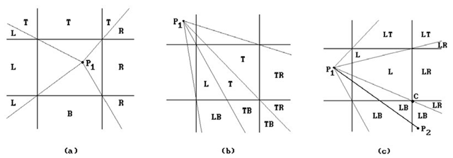
Assume that we want to clip a segment [P1,P2] against a window. The determination of the exact edges, if any, that one needs to intersect, reduces, using symmetry, to an analysis of the three possible positions of P1 shown in Figure 3.8. The cases are
(1) P1 is in the window (Figure 3.8(a)),
(2) P1is in a “corner region” (Figure 3.8(b)), or
(3) P1 is in an “edge region” (Figure 3.8(c)).
For each of these cases one determines the regions with the property that no matter where in the region the second point P2 is, the segment will have to be intersected with the same boundaries of the window. These regions are also indicated in Figure 3.8. As one can see, these regions are determined by drawing the rays from P1 through the four corners of the window. The following abbreviations were used:
|
T – ray intersects top boundary |
LT – ray intersects left and top boundary |
|
L – ray intersects left boundary |
LR – ray intersects left and right boundary |
|
B – ray intersects bottom boundary |
LB – ray intersects left and bottom boundary |
|
R – ray intersects right boundary |
TR – ray intersects top and right boundary |
|
TB – ray intersects top and bottom boundary |
For example, suppose that the segment![]() is as shown in Figure 3.8(c). Here are the computations one has to perform. Let
is as shown in Figure 3.8(c). Here are the computations one has to perform. Let![]() i and let
i and let![]() be the corner of the window also indicated in Figure 3.8(c). After checking that
be the corner of the window also indicated in Figure 3.8(c). After checking that![]() , we must determine whether the vector
, we must determine whether the vector![]() is above or below the vector
is above or below the vector![]() This reduces to determining whether the ordered basis
This reduces to determining whether the ordered basis![]() determines the standard orientation of the plane or not. Since
determines the standard orientation of the plane or not. Since
![]() is below
is below![]() We now know that we will have to compute the intersection of
We now know that we will have to compute the intersection of ![tmpc646356_thumb2_thumb[2] tmpc646356_thumb2_thumb[2]](http://what-when-how.com/wp-content/uploads/2012/06/tmpc646356_thumb2_thumb2_thumb1.png) with both the left and bottom boundary of the window.
with both the left and bottom boundary of the window.
Algorithm 3.2.4.1 is an abstract program for the Nicholl-Lee-Nicholl algorithm in the edge region case (P1 in the region shown in Figure 3.8(c)). We assume a window [xmin,xmax] x [ymin,ymax].
Figure 3.8. Nicholl-Lee-Nicholl line clipping.
Algorithm 3.2.4.1. The edge region case of the Nicholl-Lee-Nicholl line-clipping algorithm.
Algorithm 3.2.4.1. The edge region case of the Nicholl-Lee-Nicholl line-clipping algorithm.
To deal with symmetry only rotations through 90, 180, and 270 degrees about the origin and reflections about the lines x = -y and the x-axis are needed. These operations are extremely simple and involve only negation and assignment. See [NiLN87] for further details.
This finishes our survey of line-clipping algorithms. Next, we turn our attention to polygon-clipping algorithms.
Polygon-Clipping Algorithms
Sutherland-Hodgman Polygon Clipping
One of the earliest polygon-clipping algorithms is the Sutherland-Hodgman algorithm ([SutH74]). It is based on clipping the entire subject polygon against an edge of the window (more precisely, the halfplane determined by that edge which contains the clip polygon), then clipping the new polygon against the next edge of the window, and so on, until the polygon has been clipped against all of the four edges. An important aspect of their algorithm is that one can avoid generating a lot of intermediate data.
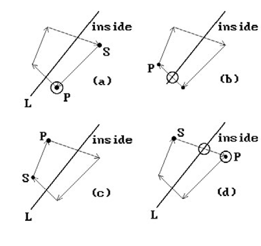
Representing a polygon as a sequence of vertices P1, P2, . . ., Pn, suppose that we want to clip against a single edge e. The algorithm considers the input vertices Pi one at a time and generates a new sequence Q1, Q2, . . ., Qm. Each Pi generates 0, 1, or 2 of the Qj, depending on the position of the input vertices with respect to e. If we consider each input vertex P, except the first, to be the terminal vertex of an edge, namely the edge defined by P and the immediately preceding input vertex, call it S, then the Q’s generated by P depend on the relationship between the edge [S,P] and the line L determined by e. There are four possible cases. See Figure 3.9. The window side of the line is marked as “inside.” The circled vertices are those that are output. Figure 3.10 shows an example of how the clipping works. Clipping the polygon with vertices labeled Pi against edge e1 produces the polygon with vertices Qi. Clipping the new polygon against edge e2 produces the polygon with vertices Ri.
Note that we may end up with some bogus edges. For example, the edge R5R6 in Figure 3.10 is not a part of the mathematical intersection of the subject polygon with the clip polygon.
Figure 3.9. The four cases in Sutherland- Hodgman polygon clipping.
Figure 3.10. A Sutherland-Hodgman polygon-clipping example.
Eliminating such edges from the final result would be a nontrivial effort, but normally they do not cause any problems. We run into this bogus edge problem with other clipping algorithms also.
An implementation of the Sutherland-Hodgman algorithm can be found in [PokG89].
Weiler Polygon Clipping
Another early polygon clipping algorithm was developed in the context of the visible surface determination algorithm in [WeiA77]. Weiler and Atherton needed a new algorithm because the Sutherland-Hodgman algorithm would have created too many auxiliary polygons. An improved version of the algorithm can be found in [Weil80]. Here is a very brief description of the algorithm:
The boundaries of polygons are assumed to be oriented so that the inside of the polygon is always to the right as one traverses the boundary. Note that intersections of the subject and clip polygon, if any, occur in pairs: one where the subject enters the inside of the clip polygon and one where it leaves.
Step 1: Compare the borders of the two polygons for intersections. Insert vertices into the polygons at the intersections.
Step 2: Process the nonintersecting polygon borders, separating those contours that are outside the clip polygon and those that are inside.
Step 3: Separate the intersection vertices found on all subject polygons into two lists. One is the entering list, consisting of those vertices where the polygon edge enters the clip polygon. The other is the leaving list, consisting of those vertices where the polygon edge leaves the clip polygon. Step 4: Now clip.
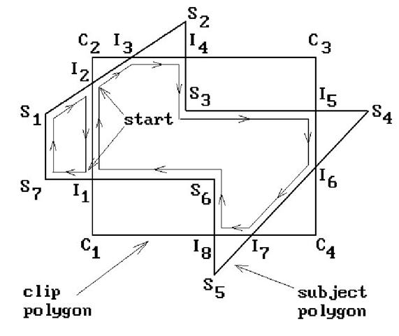
Figure 3.11. Weiler polygon clipping.
(a) Remove an intersection vertex from the entering list. If there is none, then we are done.
(b) Follow the subject polygon vertices to the next intersection.
(c) Jump to the clip polygon vertex list.
(d) Follow the clip polygon vertices to the next intersection.
(e) Jump back to the subject polygon vertex list.
(f) Repeat (b)-(e) until we are back to the starting point.
This process creates the polygons inside the clip polygon. To get those that are outside, one repeats the same steps, except that one starts with a vertex from the leaving list and the clip polygon vertex list is followed in the reverse direction. Finally, all holes are attached to their associated exterior contours.
Example. Consider the polygons in Figure 3.11. The subject polygon vertices are labeled Si, those of the clip polygon are labeled Ci, and the intersections are labeled Ii. The entering list consists of I2, I4, I6, and I8. The leaving list consists of I1, I3, I5, and I7. Starting Step 4(a) with the vertex I2 will generate the inside contour
Starting Step 4(a) with vertices![tmpc646367_thumb22[2] tmpc646367_thumb22[2]](http://what-when-how.com/wp-content/uploads/2012/06/tmpc646367_thumb222_thumb.png) will generate the outside contours
will generate the outside contours
Liang-Barsky Polygon Clipping
This section gives a brief outline of the Liang-Barsky polygon-clipping algorithm ([LiaB83]). The algorithm is claimed to be twice as fast as the Sutherland-Hodgman clipping algorithm. This algorithm and the next one, the Maillot algorithm, base their success on their ability to detect turning points efficiently. Before we get to the algorithm, some comments on turning points are in order.
Figure 3.12. Different types of turning points.
Assume that [P1,P2] is an edge of a polygon. It is easy to see that the only time that this edge is relevant to the issue of turning points is if it enters or exits a corner region associated to the window. Figure 3.12 shows some cases of polygons (the shaded regions) and how the exiting edge [P1,P2] affects whether or not the corner C becomes a turning point and needs to be added to the output. One sees the following:
(1) The analysis divides into two cases: whether the polygon is to the right or left of the edge. (Figure 3.12(a,b) versus Figure 3.12(c,d))
(2) There are two subcases that depend on which side of the ray from P2 to C the segment [P 2,P 3] is located.
(3) The decision as to whether a turning point will be needed cannot be made on the basis of only a few edges. In principle one might have to look at all the edges of the polygon first.
It is observation (3) that complicates life for polygon-clipping algorithms that process edges sequentially in one pass. One could simplify life and generate a turning point whenever we run into an edge that enters, lies in, or exits a corner region. The problem with this approach is that one will generate bogus edges for our clipped polygon. The polygon in Figure 3.12(c) would generate the “dangling” edge [B,C]. Bogus edges were already encountered in Sutherland-Hodgman clipping (but for different reasons). These edges might not cause any problems, as in the case where one is simply filling two-dimensional regions. On the other hand, one would like to minimize the number of such edges, but avoiding them entirely would be very complicated with some algorithms like the Liang-Barsky and Maillot algorithm.
With this introduction, let us describe the Liang-Barsky algorithm. We shall be brief because it does not contain much in the way of new insights given the fact that it is built on the approach they use in their line-clipping algorithm. Furthermore, another algorithm, the Maillot algorithm, is better. Our discussion here will follow [FVFH90], who have modified the algorithm so that it is easier to follow although it has the potential disadvantage of creating more bogus edges.
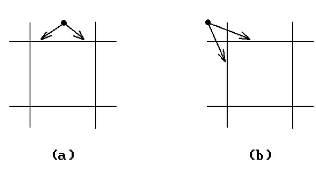
Figure 3.13. Testing for turning points.
Consider Figure 3.13. We extend the edges of our rectangular window to divide the plane into nine regions. If we are at a point of the polygon that lies in one of the four outside regions that meet the window in an edge, then the next edge of the polygon can only meet the window in that edge. See Figure 3.13(a). On the other hand, if the point is in one of the four corner regions, then the next edge could meet the window in one of two possible edges. Without look-ahead, we really cannot tell whether the adjacent corner of the window will become a turning point and will have to be added to the output polygon. In such a situation we shall play it safe and always include the corner point (even though this may create some of these unwanted edges that we have been talking about). This is the first point to make about the algorithm.
The other point is that the algorithm rests on the idea of entry and exit points for the edges of the polygon that correspond to the entry and exit values used in the line-clipping algorithm described in Section 3.2.3. By analyzing these points one can tell if an edge intersects the window or if it gives rise to a turning point. As we work our way through the edges of the polygon, assume that the current edge e = [pi,pi+1] is neither vertical nor horizontal. Then e will intersect all the boundary lines of our window. If we parameterize the line containing e in the form pi + tpipi+1, then the four intersection points correspond to four parameter values and can again be classified as two entry and two exit points. We shall denote these associated parameter values by t_in1, t_in2, t_out1, and t_out2, respectively. It is easy to see that the smallest of these is an entry value and we shall let t_in1 be that one. The largest is an exit value and we shall let t_out2 be that one. Nothing can be said about the relative size of the remaining two values in general. From Section 3.2.3 we know, however, that if t_in2 < t_out1, then the line intersects the window and if t_out2 < t_in1, then the line intersects a corner region.
If a line does not intersect the window, then it must intersect three corner regions. The conditions for that are that 0 < t_out1 < 1 and 0 < t_out2 < 1. The last statement also holds if the line intersects the window. Putting all these facts together leads to Algorithm 3.3.3.1. However, we were assuming in the discussion that edges were neither horizontal nor vertical. We could deal with such lines by means of special cases, but the easiest way to deal with them and preserve the structure of Algorithm 3.3.3.1 is to use a trick and assign dummy ±· values to the missing entering and leaving parameters. See [FVFH90].
Algorithm 3.3.3.1. Overview of a Liang-Barsky polygon-clipping algorithm.
![tmpc646353_thumb2_thumb[2] tmpc646353_thumb2_thumb[2]](http://what-when-how.com/wp-content/uploads/2012/06/tmpc646353_thumb2_thumb2_thumb1.png)


![tmpc646366_thumb22[2] tmpc646366_thumb22[2]](http://what-when-how.com/wp-content/uploads/2012/06/tmpc646366_thumb222_thumb.png)


