Introduction
Planar clipping algorithms rank as probably the second most important type of algorithm in computer graphics, following right behind line-drawing algorithms in importance. Mathematically to clip one set against another means to find their intersection. In practice, one usually wants also to get this intersection in terms of some predefined data structure.
This chapter discusses some of the well-known clipping algorithms along with some newer and more efficient ones. The algorithms fall into two types: the line-clipping algorithms, which clip single line segments against rectangular or convex regions, and polygon-clipping algorithms, which clip whole polygons against other polygons. The following terminology is used:
Definition. The polygon being clipped is called the subject polygon and the polygon that one is clipping against is called the clip polygon.
The choice of algorithms to discuss was motivated by the following considerations:
(1) It is currently one of the best algorithms of its type.
(2) It is not the best algorithm but still used a lot.
(3) The algorithm was interesting for historical reasons and easy to describe.
(4) It involved the use of some interesting techniques, even though it itself is no longer a recommended method.
Below we list the algorithms described in this chapter and categorize them by considerations (l)-(4) above. We also state any assumption regarding their clip polygon and make some comments about them. Some of the algorithms will be discussed in great detail. Others are only described very briefly, especially if they fall under heading (3) or (4) above.
|
Line-clipping algorithms: |
|||
|
|
Category |
Clip Polygon |
Comments |
|
Cohen-Sutherland |
(2) |
rectangular |
The classic line-clipping algorithm. Still popular because it is so easy to implement. |
|
Cyrus-Beck |
(4) |
convex |
|
|
Liang-Barsky |
(2) |
rectangular |
Faster than Cohen-Sutherland. |
|
Still popular. Easy to implement. |
|||
|
Nicholl-Lee-Nicholl |
(1) |
rectangular |
Purely two-dimensional. |
Polygon-clipping algorithms:
|
|
Category |
Clip Polygon |
Comments |
|
Sutherland-Hodgman |
(3) |
convex |
|
|
Weiler |
(3), (4) |
arbitrary |
|
|
Liang-Barsky |
(4) |
rectangular |
|
|
Maillot |
(1) |
rectangular |
|
|
Vatti |
(1) |
arbitrary |
Fast, versatile, and can generate a trapezoidal decomposition of the intersection. |
|
Greiner-Hormann |
(1) |
arbitrary |
As general as Vatti. Simpler and potentially faster, but no trapezoidal decomposition. |
Line-clipping algorithms fall into two types: those that use encoding of the endpoints of the segment (Cohen-Sutherland) and those that use a parameterization of the line determined by the segment (Cyrus-Beck, Liang-Barsky, and Nicholl-Lee-Nicholl). In Section 4.6 we discuss a hybrid of the two approaches that works well for the clipping needed in the graphics pipeline.
Frequently, one needs to clip more than one edge at a time, as is the case when one wants to clip one polygon against another. One could try to reduce this problem to a sequence of line-clipping problems, but that is not necessarily the most efficient way to do it, because, at the very least, there would be additional bookkeeping involved. The clipped figure may involve introducing some vertices that were not present in the original polygon. In Figure 3.1 we see that the corners A and B of the window need to be added.
Figure 3.1. Turning points in polygon clipping.
These corners are called turning points. The term was introduced in [LiaB83] and refers to the point at the intersection of two clipping region edges that has to be added to preserve the connectivity of the original polygon. This is the reason that polygon clipping is treated separately from line clipping.
Polygon-clipping algorithms fall into roughly two categories: turning-point-based algorithms like the Liang-Barsky and Maillot algorithms, which rely on quickly being able to find turning points explicitly, and the rest. Turning-point-type algorithms scan the segments of the subject polygon and basically clip each against the whole window. The rest tend to find turning points implicitly, in the sense that one does not look for them directly but that they are generated “automatically” as the algorithm proceeds. The Sutherland-Hodgman algorithm treats the clip polygon as the intersection of halfplanes and clips the whole subject polygon against each of these halfplanes one at a time. The Weiler, Vatti, and Greiner-Hormann algorithms find the turning points from the clip polygon in the process of tracing out the bounding curves of the components of the polygon intersection, although they trace the boundaries in different ways.
The chapter ends with some comments on clipping text. Some additional comments on clipping when homogeneous coordinates are used can be found in the next chapter in Sections 4.6 and 4.10.
Line-Clipping Algorithms
Cohen-Sutherland Line Clipping
This section describes an algorithm that solves the following planar clipping problem:
Given a segment [P1, P2], clip it against a rectangular window and return the clipped segment [Q1, Q] (which may be empty if the original segment lies entirely outside the window).
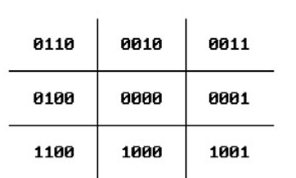
The Cohen-Sutherland line-clipping algorithm is probably the most popular of such algorithms because of its simplicity. It starts out by encoding the nine regions into which the boundary lines of the window divide the whole plane with a 4-bit binary code. See Figure 3.2. If P is an arbitrary point, then let c(P) = x3x2x1x0, where xi is either 0 or 1, define this encoding. The bits xi have the following meaning:
Figure 3.2. Cohen-Sutherland point codes.
The algorithm now has three steps:
Step 2. Check if the segment can be trivially rejected, that is, using the bitwise logical or and and operators, test whether
In case (a), the segment is entirely contained in the window since both endpoints are and the window is convex. Return![]()
In case (b), the segment is entirely outside the window. This follows because the endpoints will then lie in the halfplane determined by a boundary line that is on the other side from the window and halfplanes are also convex. Return the empty segment.
Step 3. If the segment cannot be trivially rejected, then we must subdivide the segment. We clip it against an appropriate boundary line and then start over with Step 1 using the new segment. Do the following to accomplish this: (a) First find the endpoint P that will determine the line to clip against.
(b) The line to clip against is determined by the left-most nonzero bit in c(P). For the example in Figure 3.3,![]() , and the line to clip
, and the line to clip
against is the left boundary line of the window. Let A be the intersection of the segment [P,Q] with this line.
(c) Repeat Steps 1-3 for the segment [A,Q].
The algorithm will eventually exit in Step 2.
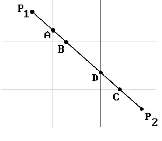
With respect to the efficiency of the Cohen-Sutherland algorithm, note that the encoding is easy since it simply involves comparing a number to some constant (the boundary lines of the window are assumed to be horizontal and vertical). Step 3 is where the real work might have to be done. We shall have to clip four times in the worst case. One such worst case is shown in Figure 3.3 where we end up having to clip successively against each one of the window boundary lines generating the intersection points A, B, C, and D.
Figure 3.3. Cohen-Sutherland line-clipping example.
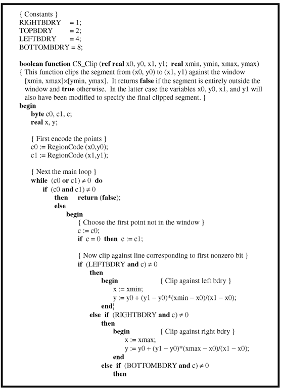
Algorithm 3.2.1.1 is an implementation of the just-described algorithm. To be more efficient, all function calls should be replaced by inline code.
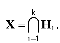
Finally, note that the encoding found in the Cohen-Sutherland line-clipping algorithm is driven by determining whether a point belongs to a halfplane. One can easily generalize this to the case where one is clipping a segment against an arbitrary convex set X. Assume that X is the intersection of halfplanes The encoding of a point P is now a k-bit number
![]() where
where
Using this encoding one can define a clipping algorithm that consists of essentially the same steps as those in the Cohen-Sutherland algorithm. One can also extend this idea to higher dimensions and use it to clip segments against cubes. See Section 4.6.
Cyrus-Beck Line Clipping
The Cyrus-Beck line-clipping algorithm ([CyrB78]) clips a segment S against an arbitrary convex polygon![]() Since X is convex, it is
Since X is convex, it is
the intersection of halfplanes determined by its edges. More precisely, for each segment denotes the point Q1) we can choose a normal vector Ni, so that X can be expressed in the form
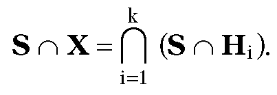
With this choice, the normals will point “into” the polygon. It follows that
In other words, we can clip the segment S against X by successively clipping it against the halfplanes Hi. This is the first basic idea behind the Cyrus-Beck clipping algorithm. The second, is to represent the line L determined by the segment S parametrically in the form and to do the clipping with respect to the parameter t.
Algorithm 3.2.1.1. The Cohen-Sutherland line-clipping algorithm.
Algorithm 3.2.1.1. The Cohen-Sutherland line-clipping algorithm.
Let Li be the line determined by the segment Define intervals
 as follows:
Case 1: L is parallel to Li.
Case 2: L is not parallel to Li.
In this case L will intersect Li in some point We distinguish between the case where the line L “enters" the halfplane Hi and where the line "exits" Hi.
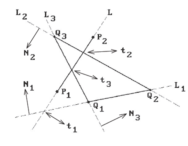
See Figure 3.4, where a segment is being clipped against a triangle
![]()
Note that finding the intersection point P in Case 2 is easy. All we have to do is solve the equation
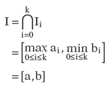
Now let Io = [ao,bo] = [0,1]. The interval Io is the set of parameters of points which lie is S. It is easy to see that the interval is the set of parameters for the points in
Figure 3.4. Cyrus-Beck line clipping.
In other words, if I is not empty, then
We shall explain this process with the example in Figure 3.4. In this example,
which clearly gives the right answer.

