Early Representation Schemes
Approaches to geometric modeling have changed over the years. These changes began before computers existed and all one had was pencil and paper. Since the advent of computers, these changes were largely influenced by their power, the essential mathematics behind the changes being basically not new. As computers become more and more powerful, it gradually becomes possible to implement mathematical representations that mathematicians have used in their studies. The history of the development of geometric modeling shows this trend. Of course, the new ways of interactively visualizing data that was not possible before will undoubtedly cause its own share of advances in knowledge. We shall comment more on this at the end of this topic.
Engineering Drawings. Engineering drawings were the earliest attempts to model objects. Computers were not involved and they were intended as a means of communication among humans. They often had errors but humans were able to use common sense to end up with correct result. There was no formal definition of such drawings as a representation scheme. The basic idea was to represent objects by a collection of planar projections. As such it is a highly ambiguous representation scheme because if one were to try to implement it on a computer, it is very difficult to determine how many two-dimensional projections would be needed to completely represent a three-dimensional object. Constructing an object from some two-dimensional projections of it is a highly interesting and difficult problem. We touched on two small aspects of this problem in Section 4.12. For more, see [RogA90], [BoeP94], [PenP86], or [Egga98].
Wireframe Representations. Wireframe representations were the first representation schemes for three-dimensional linear polyhedra. It is a natural approach, the idea being to represent them using only their edges.
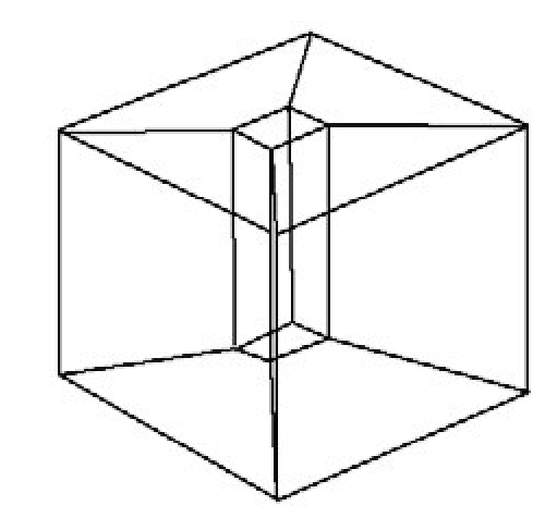
Figure 5.8. An ambiguous wireframe representation.
After all, edges are some of the most important features of an object that one “sees.” Unfortunately, this representation scheme is ambiguous. For example, Figure 5.8 shows a block with a beveled hole through its center. It is not possible to tell along which axis the hole lies from the edge information alone. Two problems caused by the ambiguity are that one cannot remove hidden lines reliably and one cannot produce sections automatically.
Many early commercially available modeling systems used wireframe representations. Even now many systems support a wireframe display mode because it is fast and adequate for some jobs. A wireframe display is one where only edges and no faces are shown. Note that how objects are displayed is quite independent of how they are represented internally.
Faceted Representations. A simple solution that eliminates the major wireframe representation problems for three-dimensional objects is to add faces. This representation is unambiguous. We shall look at this approach in more detail later in the section on the boundary representation. Again, there is a difference between a modeling system using a faceted representation and one using a faceted display. The latter means that objects (of all dimensions) are displayed as if they were linear polyhedra even though the system may maintain an exact analytic representation of objects internally. For example, a sphere centered at the origin is completely described by one number, its radius, but it might be displayed in a faceted manner.
Attempts have been made to develop algorithms that generate faces from a wireframe representation automatically, but it is known that only using topological information leads to an NP-complete problem, so that the algorithms will not be very efficient in general. See, for example, [BagW95].
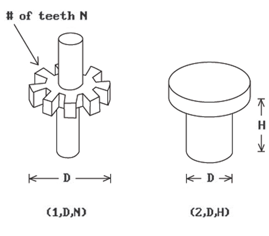
Primitive Instancing Schemes. In this scheme we simply have a finite number of generic parameterized primitives that can be represented via tuples of the form (type code, parameter 1 , . . ., parameter k) where the parameters are either reals or integers. See Figure 5.9. We do not need all dimensions as parameters, only those that are variable. The representation is unambiguous and may be unique. It is certainly very compact. With regard to algorithms for computing properties of objects represented by such scheme, one basically needs a special case for each primitive.
Figure 5.9. Primitive instancing scheme.
A primitive instancing scheme is only really useful when the number of primitives is small. The scheme is similar to a language in which words cannot be combined to make a sentence. Note that a good structured modeling system can achieve all the advantages of a primitive instancing scheme by providing a macro capability.
Boundary Representations
Since one only sees the surface of solids, it is natural to represent them via their boundary. Mathematically this is justified because in the special case of closed and bounded solids in Rn the boundary of a solid uniquely defines that solid. (In general, though, the boundary of a manifold does not define the manifold.)
Definition. The boundary representation or b-rep of r-sets in Rn is the representation that associates to each r-set X its boundary bX. More generally, a b-rep for r-sets is a representation that associates to an r-set X a representation of bX.
B-reps are probably the most common representations used in computer graphics. If X is a solid in R3, then
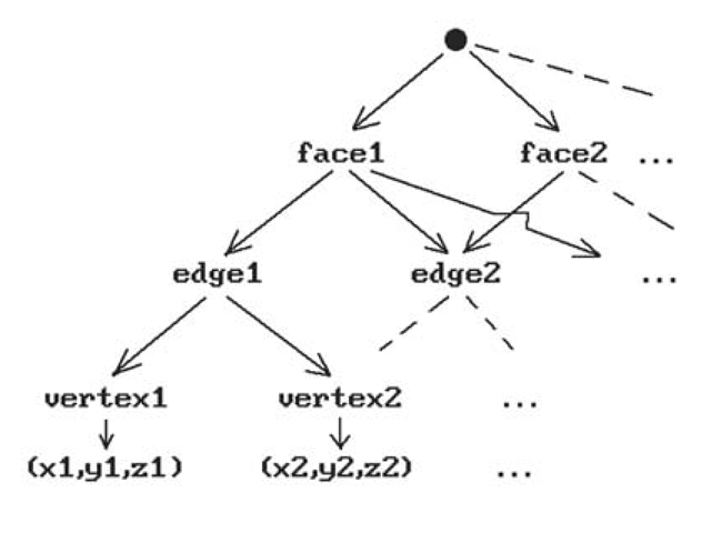
The boundary of each face is itself a union of edges and the boundary of an edge is a set of two points. One can therefore think of a boundary representation scheme for solids in terms of a relation between objects and certain graphs. See Figure 5.10 for the most basic version of such a graph. For linear polyhedra it is actually a function. For curved objects it is not a function because it depends on how the boundary of the object is divided into cells (curved patches).
There are some difficult questions having to do with the validity of boundary representations. In particular,
When does a graph of the type shown in Figure 5.10 come from a real polyhedron?
Figure 5.10. A boundary representation graph.
There is no easy answer to this question. Here are some conditions in case the b-rep for a solid is supposed to be induced from a simplicial decomposition, that is, the solid is the underlying space of a simplicial complex:
(1) Each face must have three edges.
(2) Each edge must have two vertices.
(3) Each edge must belong to an even number of faces.
(4) Each vertex of a face must belong to precisely two edges of the face.
(5) All points (x,y,z) must be distinct.
(6) Edges must be disjoint or intersect in a vertex.
(7) Faces must be disjoint or intersect in edges.
Conditions (1)-(4) deal with the combinatorial topology of simplicial complexes and are easy to check. Conditions (5)-(7) are point set topology questions that are expensive to test.
Some common data structures that are used to implement the boundaries of linear polyhedra are described in Section 5.8.1.
The CSG Representation
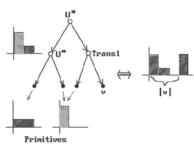
In constructive solid geometry (CSG) one represents objects in terms of a sequence of Boolean set operations and rigid motion operators starting with a given collection of primitive objects. One can express this representation pictorially as a binary tree. For example, in Figure 5.11 the binary tree on the left is used to represent the union of three blocks, one of which has been translated by a vector v. Although the idea is simple enough, we must get a little technical in order to give a precise definition.
Let P be a set of r-sets in Rn. The elements of P will be called primitive objects. Let O be a set of regularized binary set operators such as![]() Let M be a set of pairs (m,x) where m is a label for a rigid motion of Rn such as a translation, rotation, . . ., andx is data that defines a specific such motion. For example, if n = 2, then (rotation
Let M be a set of pairs (m,x) where m is a label for a rigid motion of Rn such as a translation, rotation, . . ., andx is data that defines a specific such motion. For example, if n = 2, then (rotation is a possible pair in M and represents the rotation of R2 about p through an angle
![]() If
If![]() then let m(x) denote the rigid motion defined by the pair (m,x).
then let m(x) denote the rigid motion defined by the pair (m,x).
Figure 5.11. A CSG example.
Definition. A CSG-tree for the tuple (Ρ,Ο,Μ) is an expression T defined recursively in BNF (Backus-Naur Form) notation by
An informal definition of a CSG-tree is
It is clear that a CSG-tree can be identified with a binary tree like the one shown in Figure 5.11 and that is what is usually done in practice. Some typical values that have been used for P, O, and M are
Definition. The realization of a CSG-tree T is the space ITI defined recursively as follows:
Definition. The CSG representation or csg-rep for a tuple (Ρ,Ο,Μ) is the representation of r-sets using CSG-trees which consists of pairs (X,T) where X is an r-set, T is a CSG-tree for (Ρ,Ο,Μ), and X = ITI.
Although one is free to choose any set of primitives or transformations for a csg-rep, generic halfspaces of one sort or another are usually used as primitives. Two common csg-reps used
(1) "arbitrary" (possibly unbounded) generic halfspaces as primitives, or
(2) bounded generic halfspace combinations as primitives.
Primitives are often parameterized. For example, a primitive block is usually considered to be situated at the origin and to be defined by the three parameters of length, width, and height. One then talks about instancing a primitive, where that term means
(1) assigning values to the configuration parameters, and then
(2) positioning the result of (1) via a rigid motion (which could also be viewed as assigning values to positional parameters).
Csg-reps can handle nonmanifold objects. Their exact domain of coverage depends on
(1) the primitives (actually the halfspaces which define them),
(2) the motion operators that are available, and
(3) the set operators that are available.
It is interesting to note the results of an extensive survey of mechanical parts and what it takes to describe them which can be found in [SaRE76]. Fully 63% of all the parts could be handled with a CSG system based on only orthogonal block and cylinder primitives. A larger class of primitives provided a natural description of over 90% of the parts. This indicated that CSG is therefore a good fit for a CAD system in that sort of environment because most mechanical parts seemed to be relatively simple.
If one uses general operations and bounded primitives, then one gets a representation that is
(1) unambiguous,
(2) not unique,
(3) very concise, and
(4) easy to create (at least for its domain of coverage).
One of the biggest advantages of a csg-rep over other representation schemes is that validity is pretty much built into the representation if one is a little careful about choosing primitives. For example, if one uses r-sets as primitives and arbitrary regularized set operations, then the algebraic properties of r-sets ensure that a representation is always valid. This is not the case if operations are not general, for example, if the union operation is only allowed for quasi-disjoint objects. Also, in a CSG system based on general generic halfspaces, some trees may represent unbounded sets and hence not be valid. It is true however that, by in large, all syntactically correct CSG representations (trees) are also semantically correct.
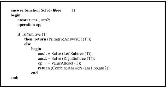
Because of the tree structure of a CSG representation, one can often use a divide-and-conquer approach to algorithms: one first solves a problem for the primitive objects and then uses recursion. See Algorithm 5.3.3.1. The point membership classification function, which is discussed in Section 5.9, is an example of this.
Algorithm 5.3.3.1. A divide-and-conquer approach in CSG.
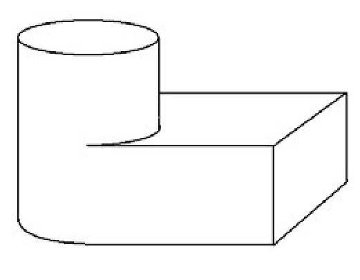
Figure 5.12. What are the faces of this solid?
One disadvantage with a CSG representation is that it is not easy to generate a display using it because one needs the boundary of an object for that. Getting a boundary representation for an object defined by CSG (a process referred to as boundary evaluation) is relatively hard. We look at this in more detail in Section 5.9. One problem in this context (especially for mechanical design) is how to define a “face” of an object. This certainly is no problem in the linear case, but it is for curved objects. See Figure 5.12. What should the faces be in that figure? Some minimal characteristics of a face are:
(1) A face should be contained in the boundary of the solid.
(2) Topologically, a face should be a surface with boundary.
(3) If the solid was defined via regularized Boolean set operations from a collection of halfspaces {Hi}, then each face should be contained in bHi for some i.
(4) Faces should be quasi-disjoint, that is, pairwise intersections of faces should either be empty or lie in their boundary.
Another issue when it comes to faces is how to represent them? We shall see in Section 5.9 that to represent a face F we can
(1) represent the halfspace in whose boundary the face F lies (for example, in the case of a cylinder, use its equation),
(2) represent the boundary edges of F (the boundary of a face is a list of edges), and
(3) maintain some neighborhood information for these bounding edges and orient the edges (for example, we can arrange it so that the inside of the face is to the right of the edge or we can store appropriate normal vectors for the edges).
This scheme works pretty well for simple surfaces but for more complicated surfaces one needs more.
